Cantilever beam – Moments and Forces (Handcalculation)
As we used FE programs to calculate the bending moments, forces and deflections of structures in last tutorials, we are going a step back now to the very basics of structural engineering and do hand calculations: We start with one of the most used static systems – the cantilever beam.
In this post we’ll go through, step-by step, how to calculate forces and moments of cantilevers for different loading situations.
Not much more talk, let’s dive into it.
🙋♀️ What is a cantilever or a cantilever beam?
A cantilever is a static system acting as a beam in bending and shear. Therefore it is also called a canteliver beam. It is characterized by having only one support – a fixed – on one of the two ends.
We are surrounded by cantilevers in our daily lives. The probably most seen example of cantilevers are balconies.
Here are 10 examples of cantilevers
- Traffic light posts and systems cantilevering over the street
- Overhangs of roofs
- Construction of bridges with the balanced cantilever method
- Balconies
- Aeroplane wings
- Side mirrors on a car
- High-rise buildings (vertical cantilevers)
- Bookshelves attached to the wall
- Cranes
- Wind turbine blades
👆 The static system of the cantilever
The cantilever is in most cases a horizontal beam having a fixed support on the one end and no support on the other end. The cantilever can take both bending moments and shear forces.
Let’s have a look at the static system.
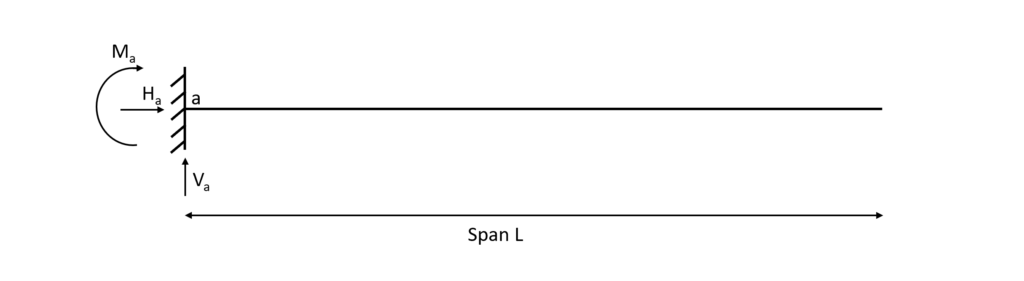
It can be seen from the picture that the fixed support (a) takes up
- a moment reaction M
- a vertical reaction force V and
- a horizontal reaction force H
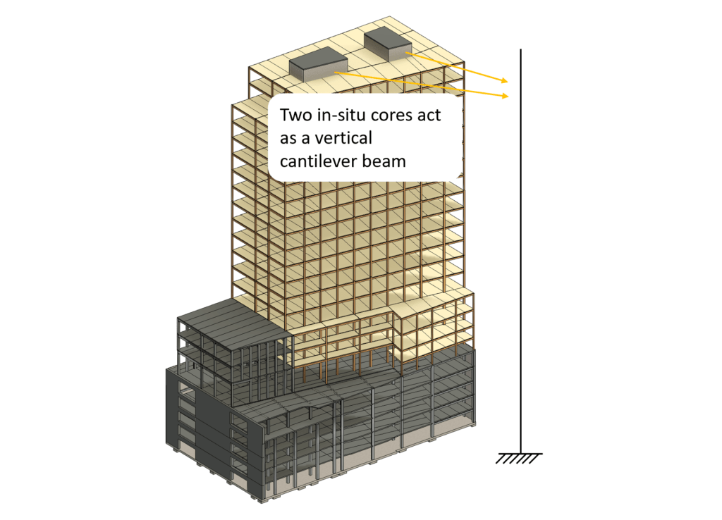
🏢 The static system applied to real structures
Understanding the static system of a structure is probably one of the hardest parts about statics and structural engineering in the beginning.
From my experience it’s also poorly taught at university and there is very little information about it online as well, isn’t it?
So let’s look at some applied examples.
- Highrise in-situ concrete cores as vertical cantilevers to stiffen the building when exposed to horizontal loads (wind, earthquakes)
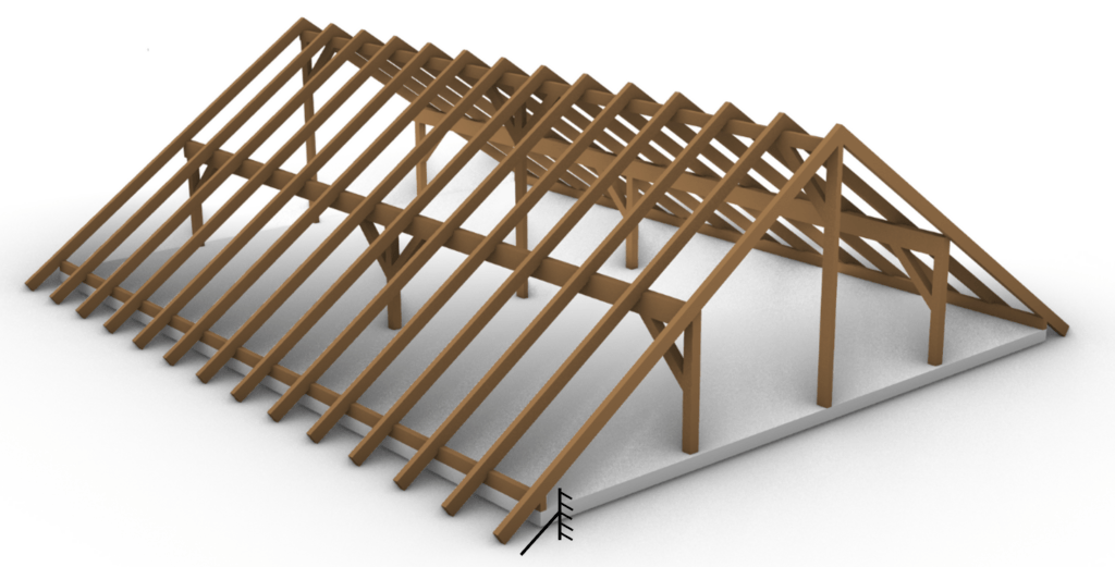
- The overhang of rafters of purlin roofs can also be seen as a cantilever beam. However it’s more common to say that the rafters are a continuous beam with a cantilevered overhang.
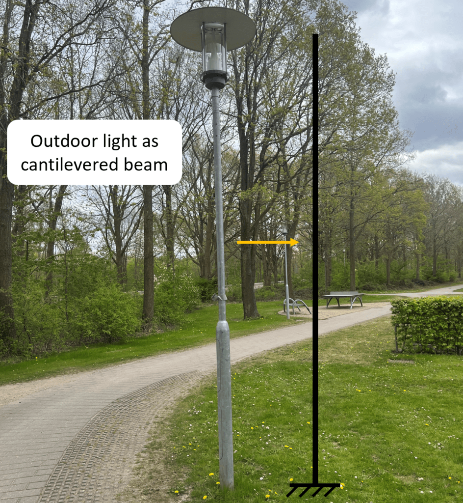
- Outdoor light and traffic light posts are vertical cantilever beams.
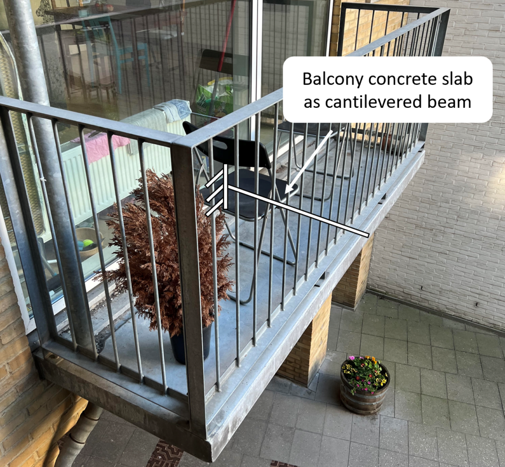
- Balconies are often built as cantilevers. When we talk about balconies we would say cantilever slabs, however, in most cases the 3D structure is transformed into a 2D system, as we’ll see in the following.
⬇️ 2 Examples of loading situations
We want to keep it a bit joyful and realistic in this blog, right? So let’s look at loading scenarios we all can relate to.
🧍 Me standing on my balcony – A Point load
Let’s look at the example where a person – in this case me😊 – stands on the balcony and let’s assume that i weigh 75 kg.
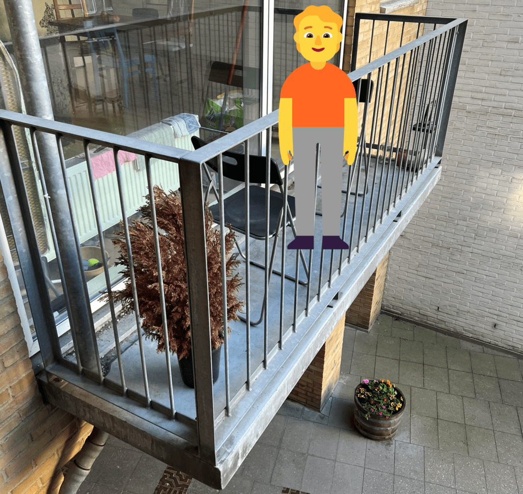
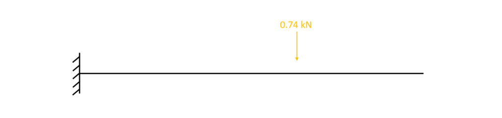
This weight of 75 kg can directly be translated into 0.74 kN. Now because I stand in a specific point with my two legs, the load is concentrated and therefore the 0.74 kN equals a point load on the cantilever slab.
As we saw in the previous section, the slab equals a beam, and we can therefore apply the Point load on a cantilever beam.
🏋️ The self-weight of a balcony – Area or Line load
So.. the balcony has a self-weight, right? In structural engineering we also call this dead load and it’s always equally/uniformly distributed for horizontal elements.
For the case of the concrete balcony, the self-weight per $m^2$ is calculated as
$Density \cdot thickness = 2400 kg/m^3 * 200mm = 4.7 kN/m^2 $
Now, it always helps to translate kN in non-engineering language. $4.7kN/m^2$ is also 470 kg per $m^2$.
That’s as much as a piano or a horse – but only per square meter! So in case of our balcony where we have roughly $3m^2$ the dead load of the concrete is equal to 3 horses.
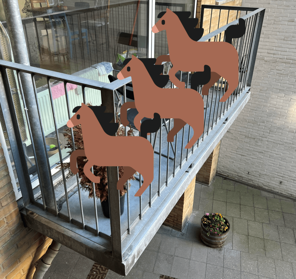
It’s a lot, right? Compared to me as a pointload of 75 kg🧍
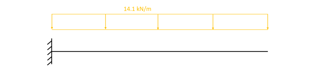
In order to use our 2D static system, the Area load – a load per m2 – needs to be transformed in a Line load – a load per meter (m).
This is done by multiplying the Area load (kN/m2) with the width of the balcony, which is 3 m.
$g_k = 4.7 kN/m^2 * 3m = 14.1 kN/m$
🧮 Hand calculation of bending moment and shear forces – cantilever
Now in order to design the thickness and material properties of the balcony – or any other (cantilevered) structure the forces and moments acting in the beam need to be calculated.
In general, statically determinate structures such as the cantilever or the simply supported beams need to fullfill three equilibrium conditions:
- Horizontal equilibrium $\sum H = 0$: The sum of all horizontal loads and reactions is 0.
- Vertical equilibrium $\sum V = 0$: The sum of all vertical loads and reactions is 0.
- Moment equilibrium $\sum M = 0$: The sum of all moments is 0.
Let’s continue with the 2 loading situations that we are now familiar with – point and line load.
🔎 Bending moment and shear forces due to Point load
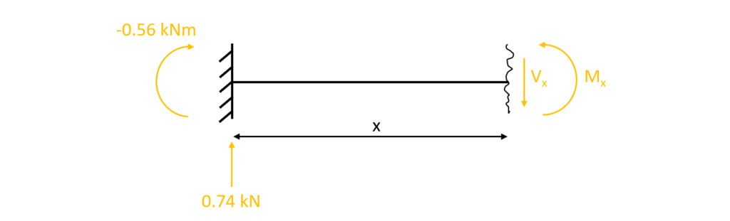
1. The first thing we always calculate in determinate structures are the reaction forces/moment. In our case that is $V_a, H_a$ and $M_a$ at the support A due to the equilibrium conditions.
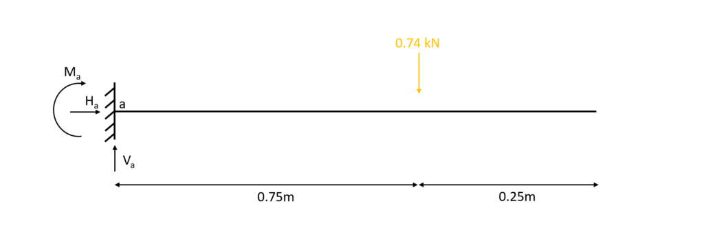
$\sum H = 0: H_a = 0$
$\sum V = 0: V_a – 0.74 kN = 0$ -> $V_a = 0.74 kN$
$\sum M = 0: M_a + 0.74 kN \cdot 0.75m = 0$ -> $M_a = -0.56 kNm$
2. Based on the reaction forces, the shear and moment distribution along the beam can be calculated. This can also be done without the reaction forces for the cantilevered beam. The parameter x is introduced as the length between point a and any point on the beam.
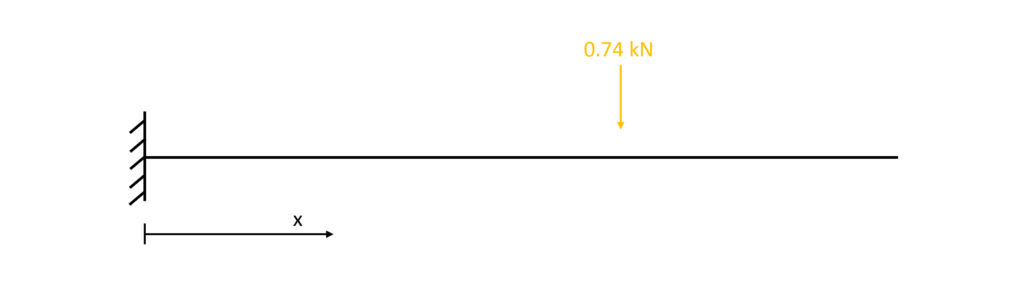
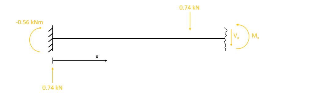
3. The shear forces and bending moments can be calculated in dependence of x. Let’s make a first cut at a point between the support and the point load 0<x<0.75m.
As for the reaction force calculation, the equilibrium conditions are used to calculate the moment and shear forces at point x
$\sum H = 0: H_a = 0$
$\sum V = 0: 0.74 kN – V_x = 0$ -> $V_x = 0.74 kN$
$\sum M = 0: M_x – (-0.56 kNm) – 0.74 kN \cdot x = 0$ -> $M_x = -0.56 kNm + 0.74 kN \cdot x$
As we can see the shear force is constant and not dependent on the parameter x. Let’s set x = 0.5m and see what results we get for the bending moment:
$M_{0.5m} = -0.56 kNm + 0.74 kN \cdot 0.5m = -0.19 kNm$
4. Cut at a point between the point load and the endpoint 0<x<0.75m
The equilibrium conditions lead to
$\sum H = 0: H_a = 0$
$\sum V = 0: 0.74 kN – V_x – 0.74 kN = 0$ -> $V_x = 0 kN$
$\sum M = 0: M_x – (-0.56 kNm) – 0.74 kN \cdot x + 0.74 kN \cdot (x-0.75m) = 0$
$M_x = -0.56 kNm + 0.74 kN \cdot x – 0.74 kN \cdot x + 0.74 kN \cdot 0.75m = 0$

.. and in this picture it’s obvious very quickly that the bending moment and shear force equal 0.
5. Bending moment and shear force diagrams
The diagrams can be plotted by a tool like Excel using the formulas from above or drawn by hand when one is aware of the geometrical shape of the distribution.
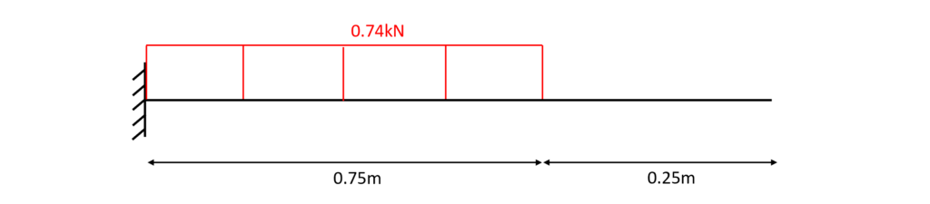
Shear force diagram – cantilever
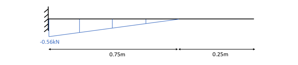
Bending moment diagram – cantilever
👨🏫 Bending moment and shear forces due to Line load
1.As for the Point load, we first calculate the reaction forces $V_a, H_a$ and moment $M_a$ in the determinate structure – cantilever beam – due to the equilibrium conditions.
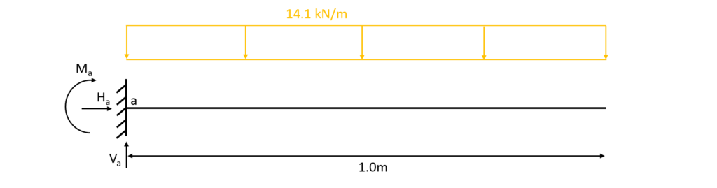
$\sum H = 0: H_a = 0$
$\sum V = 0: V_a – 14.1 kN/m \cdot 1.0m = 0$ -> $V_a = 14.1 kN$
$\sum M = 0: M_a + 14.1 kN/m \cdot 1.0m \cdot 0.5m = 0$ -> $M_a = -7.05 kNm$
2. Calculation of the shear and moment distribution along the beam due to the reaction forces. This can also be done without the reaction forces for the cantilever beam. The parameter x is introduced as the length between point a and any point on the beam.

3. The shear forces and bending moments can be calculated in dependence of x. Let’s make a cut at a point between the support and the end point of the cantilever 0<x<1.0m.
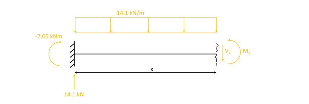
As for the reaction force calculation, the equilibrium conditions are used to calculate the moment and shear forces at point x.
$\sum H = 0: H_a = 0$
$\sum V = 0: V_x + 14.1 kN/m \cdot x – 14.1 kN = 0$ -> $V_x = 14.1kN – 14.1 kN/m \cdot x$
$\sum M = 0: M_x – (-7.05 kNm) – 14.1 kN \cdot x + 14.1 kN/m \cdot \frac{x^2}{2} = 0$ -> $M_x = -7.05 kNm + 14.1 kN \cdot x – 14.1 kN/m \cdot \frac{x^2}{2}$
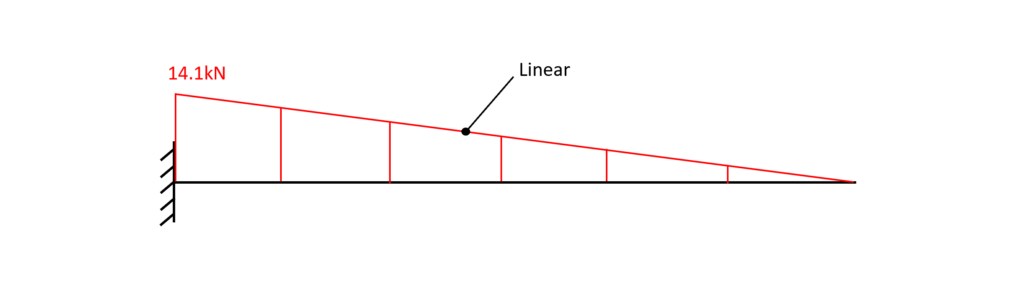
Compared to the distribution due to a point load, the shear force distribution is now linear and dependent on the parameter x.
Let’s set x = 0.5m and see what results we get for the shear force and bending moment:
$V_{0.5m} = 14.1 kN – 14.1 kN \cdot 0.5m = 7.05 kN$
$M_{0.5m} = -7.05 kNm + 14.1 kN \cdot x – 14.1 kN/m \cdot \frac{x^2}{2} = -1.76 kNm$
4. Bending moment and shear force diagrams
The diagrams can be plotted by a tool like Excel using the formulas from above or drawn by hand when one is aware of the geometrical shape of the distribution.
Shear force diagram – cantilever
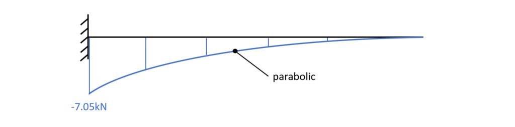
Bending moment diagram – cantilever
Once the forces and moments are calculated, the design of the element needs to be done.
In our case that is the concrete and rebar design of the balcony, meaning that we pick the concrete type, calculate the amount of rebars required and verify the height of the cross-section.
Now, I would like to hear from you: What cantilever do you know from the “real world”? Did I forget some? Let us know in the comments below📝
![Howe Truss [A Structural Guide]](https://www.structuralbasics.com/wp-content/uploads/2022/12/Howe-truss-768x439.jpg)
![Understand Bending Moments [Everything YOU Need To Know – 2026]](https://www.structuralbasics.com/wp-content/uploads/2023/05/Bending-moment-768x439.jpg)
![Arch – Moment And Normal Force Calculation Due To Line Load [A Guide]](https://www.structuralbasics.com/wp-content/uploads/2022/05/Arch-Structure-Internal-Force-Calculation-Due-To-Line-Load-768x439.jpg)
This is a topic that’s close to my heart…
Cheers! Where are your contact details though?
Cheers Alycia!
My contact details are here: https://www.structuralbasics.com/contact/