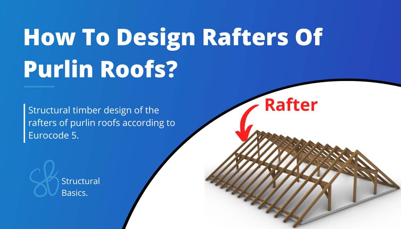
How To Dimension Rafters Of Purlin Roofs? [Structural Guide]
We have now finally covered all the basics like wind load, snow load, dead load, load combinations, directions of loads and statical systems of roofs. In this article we can use that knowledge to dimension rafters🎉
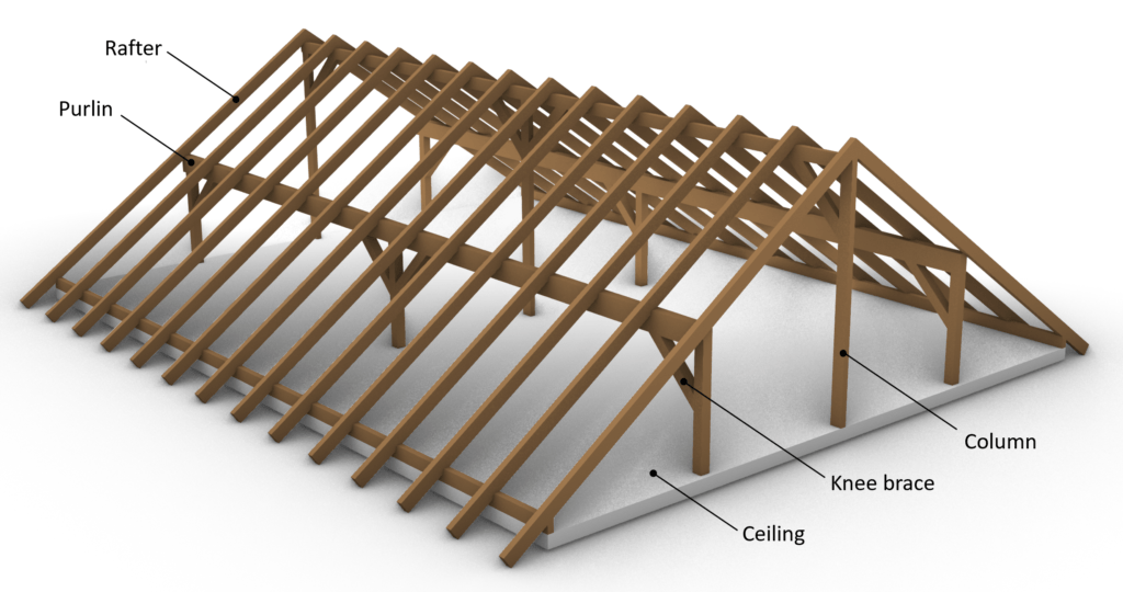
To be on the same page, we should first describe what a purlin roof is, and what are the rafters of it? 🤔
I know all this sounds quite complicated, but don’t worry, we will explain it practically with examples and pictures.
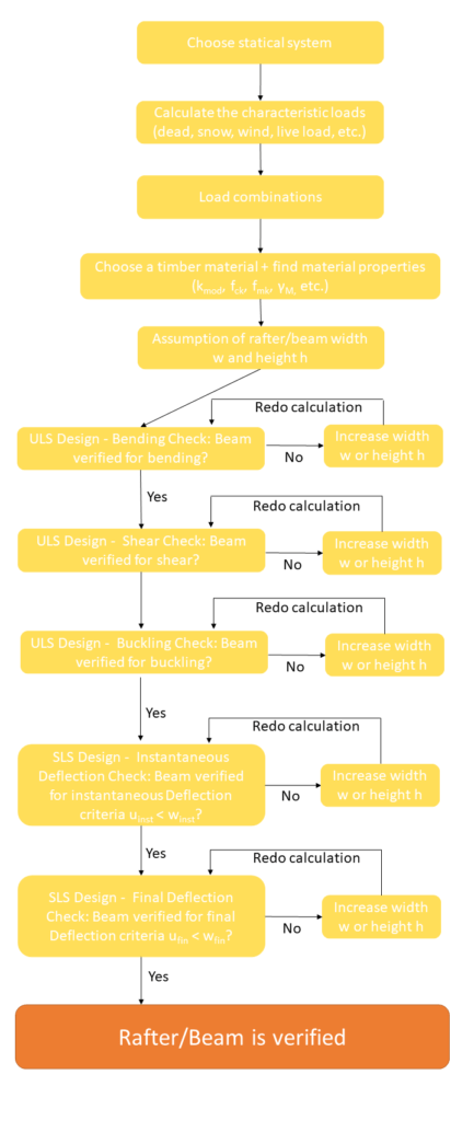
Let me explain to you the steps we have to do to dimension a rafter. Let’s take a look at the steps we need to follow.
If you are a visual person like me, I also made a process chart after the bullet points🖼️.
- Choose a right statical system, continous beam in our case
- Calculate all characteristic loads (dead, snow, wind, live load, etc.)
- Calculate all load combinations
- Choose a timber material and find material properties ($k_{mod}$, $f_{c.0.k}$, $f_{m.k}$, $\gamma_{M}$)
- Assume the width w and height h of the cross section
- Verify the beam for bending (with compression or tension). If not verified increase the width or height of the beam and do the calculation again
- Verify the beam for shear. If not verified increase the width or height of the beam and do the calculation again
- Verify the beam for buckling. If not verified increase the width or height of the beam and do the calculation again.
- Verify the beam for the instantaneous deflection criteria. If not verified increase the width or height of the beam and do the calculation again
- Verify the beam for the final deflection criteria. If not verified increase the width or height of the beam and do the calculation again
- If all of those checks are now verified, then you have figured out the correct dimensions of the beam
Static system
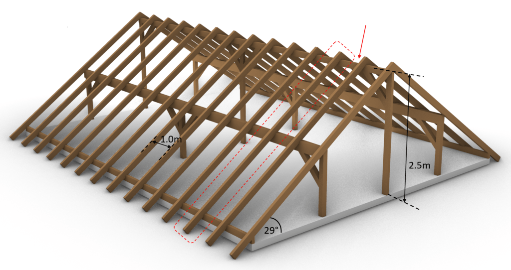
The purlin roof has in fact more than one static system. We will focus on the rafters and its statical system in this article.
But the support forces of the rafter beams are applied to the purlins and its statical system. We will touch base on the purlin design in the next blog post.
The static system of the rafters of our example can be visualized as in the next picture.
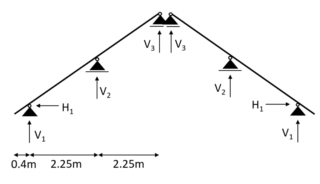
To not lose context – the 2D static system represents the following rafters.
But it can also represent any other rafters except the first and the last row at the gables, because those take less loads. The spacing between the rafters is set to 1 m.
The purlin roof can of course also have different layouts with more or less supports and different spans.
Loads
The loads will not be derived in this article. We explained the calculation of dead, live, wind and snow loads for pitched roofs thoroughly in previous articles. The defined load values are estimations from the previous calculations.
| $g_{k}$ | 1.08 kN/m2 | Characteristic value of dead load |
| $q_{k}$ | 1.0 kN/m2 | Characteristic value of live load |
| $s_{k}$ | 0.53 kN/m2 | Characteristic value of snow load |
We will split up the wind load from the above table due to the complexity of the wind with its wind areas and directions. In this calculation, we will only focus on the external wind pressure for areas of 10 m2.
Wind direction front
| $w_{k.F}$ | -0.25(/0.35) kN/m2 | Characteristic value of wind load Area F |
| $w_{k.G}$ | -0.25(/0.35) kN/m2 | Characteristic value of wind load Area G |
| $w_{k.H}$ | -0.1(/0.2) kN/m2 | Characteristic value of wind load Area H |
| $w_{k.I}$ | -0.2(/0.0) kN/m2 | Characteristic value of wind load Area I |
| $w_{k.J}$ | -0.25(/0.0) kN/m2 | Characteristic value of wind load Area J |
Wind direction side
| $w_{k.F}$ | -0.55 kN/m2 | Characteristic value of wind load Area F |
| $w_{k.G}$ | -0.7 kN/m2 | Characteristic value of wind load Area G |
| $w_{k.H}$ | -0.4 kN/m2 | Characteristic value of wind load Area H |
| $w_{k.I}$ | -0.25 kN/m2 | Characteristic value of wind load Area I |
Load combinations
Luckily we have already written an extensive article about what load combinations are and how we use them. In case you need to brush up on it you can read the blog post here.
We are choosing to include $w_{k.H.}$ = -0.4 kN/m2 as the wind load in the load combinations and the following calculations to keep it clean.
In principle, you should consider all load combinations. However, with a bit more experience, you might be able to exclude some of the values.
In modern FE programs, multiple values for the wind load can be applied, and load combinations automatically generated.
So the computer is helping us a lot. Just keep in mind that you should include all wind loads but because of simplicity we do only consider 1 value in this article😁
ULS Load combinations
I know you might not understand what that means when you do load combinations the first time, but we did a whole article about what loads exist and how to apply them on a pitched roof 😎.
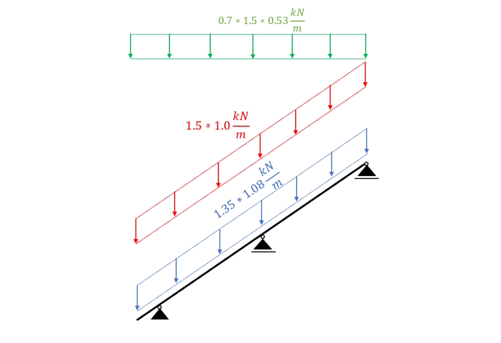
| LC1 | $1.35 * 1.08 \frac{kN}{m^2} $ |
| LC2 | $1.35 * 1.08 \frac{kN}{m^2} + 1.5 * 1.0 \frac{kN}{m^2}$ |
| LC3 | $1.35 * 1.08 \frac{kN}{m^2} + 1.5 * 1.0 \frac{kN}{m^2} + 0.7 * 1.5 * 0.53 \frac{kN}{m^2}$ |
| LC4 | $1.35 * 1.08 \frac{kN}{m^2} + 0 * 1.5 * 1.0 \frac{kN}{m^2} + 1.5 * 0.53 \frac{kN}{m^2}$ |
| LC5 | $1.35 * 1.08 \frac{kN}{m^2} + 1.5 * 1.0 \frac{kN}{m^2} + 0.7 * 1.5 * 0.53 \frac{kN}{m^2} + 0.6 * 1.5 * (-0.4 \frac{kN}{m^2}) $ |
| LC6 | $1.35 * 1.08 \frac{kN}{m^2} + \Psi_{0} * 1.5 * 1.0 \frac{kN}{m^2} + 1.5 * 0.53 \frac{kN}{m^2} + 0.6 * 1.5 * (-0.4 \frac{kN}{m^2}) $ |
| LC7 | $1.35 * 1.08 \frac{kN}{m^2} + 0 * 1.5 * 1.0 \frac{kN}{m^2} + 0.7 * 1.5 * 0.53 \frac{kN}{m^2} + 1.5 * (-0.4 \frac{kN}{m^2}) $ |
| LC8 | $1.35 * 1.08 \frac{kN}{m^2} + 1.5 * 0.53 \frac{kN}{m^2} $ |
| LC9 | $1.35 * 1.08 \frac{kN}{m^2} + 1.5 * (-0.4 \frac{kN}{m^2}) $ |
| LC10 | $1.35 * 1.08 \frac{kN}{m^2} + 1.5 * 1.0 \frac{kN}{m^2} + 0.6 * 1.5 * (-1.0 \frac{kN}{m^2}) $ |
| LC11 | $1.35 * 1.08 \frac{kN}{m^2} + 1.5 * (-0.4 \frac{kN}{m^2}) + 0.7 * 1.5 * 0.53 \frac{kN}{m^2} $ |
| LC12 | $1.35 * 1.08 \frac{kN}{m^2} + 1.5 * 0.53 \frac{kN}{m^2} + 0.6 * 1.5 * (-0.4 \frac{kN}{m^2})$ |
Characteristic SLS Load combinations
| LC1 | $1.08 \frac{kN}{m^2} $ |
| LC2 | $1.08 \frac{kN}{m^2} + 1.0 \frac{kN}{m^2}$ |
| LC3 | $1.08 \frac{kN}{m^2} + 1.0 \frac{kN}{m^2} + 0.7 * 0.53 \frac{kN}{m^2}$ |
| LC4 | $1.08 \frac{kN}{m^2} + 1.0 \frac{kN}{m^2} + 0.6 * (-0.4 \frac{kN}{m^2})$ |
| LC5 | $1.08 \frac{kN}{m^2} + 1.0 \frac{kN}{m^2} + 0.7 * 0.53 \frac{kN}{m^2} + 0.6 * (-0.4 \frac{kN}{m^2}) $ |
| LC6 | $1.08 \frac{kN}{m^2} + 0 * 1.0 \frac{kN}{m^2} + 0.53 \frac{kN}{m^2} + 0.6 * (-0.4 \frac{kN}{m^2}) $ |
| LC7 | $1.08 \frac{kN}{m^2} + 0 * 1.0 \frac{kN}{m^2} + 0.7 * 0.53 \frac{kN}{m^2} + (-0.4 \frac{kN}{m^2}) $ |
| LC8 | $1.08 \frac{kN}{m^2} + 0.53 \frac{kN}{m^2}$ |
| LC9 | $1.08 \frac{kN}{m^2} + (-0.4 \frac{kN}{m^2}) $ |
| LC10 | $1.08 \frac{kN}{m^2} + 1.0 \frac{kN}{m^2} + 0.6 * (-0.4 \frac{kN}{m^2}) $ |
| LC11 | $1.08 \frac{kN}{m^2} + (-0.4 \frac{kN}{m^2}) + 0.7 * 0.53 \frac{kN}{m^2} $ |
| LC12 | $1.08 \frac{kN}{m^2} + 0 * 1.0 \frac{kN}{m^2} + 0.53 \frac{kN}{m^2}$ |
| LC13 | $1.08 \frac{kN}{m^2} + 0 * 1.0 \frac{kN}{m^2} + (-0.4 \frac{kN}{m^2})$ |
Rafter timber material
For this blog post/tutorial we are choosing a Structural timber C24. More comments on which timber material to pick and where to get the properties from were made here. The following characteristic strength and stiffness parameters were found online from a manufacturer.
| Bending strength $f_{m.k}$ | 24 $\frac{N}{mm^2}$ |
| Tension strength parallel to grain $f_{t.0.k}$ | 14 $\frac{N}{mm^2}$ |
| Tension strength perpendicular to grain $f_{t.90.k}$ | 0.4 $\frac{N}{mm^2}$ |
| Compression strength parallel to grain $f_{c.0.k}$ | 21 $\frac{N}{mm^2}$ |
| Compression strength perpendicular to grain $f_{c.90.k}$ | 2.5 $\frac{N}{mm^2}$ |
| Shear strength $f_{v.k}$ | 4.0 $\frac{N}{mm^2}$ |
| E-modulus $E_{0.mean}$ | 11.0 $\frac{kN}{mm^2}$ |
Modification factor $k_{mod}$
If you do not know what the modification factor $k_{mod}$ is, we wrote an explanation to it in a previous article which you can check out.
Since we want to keep everything as short as possible, we are not going to repeat it in this article – we are only defining the values of $k_{mod}$.
For a residential house which is classified as Service class 1 according to EN 1995-1-1 2.3.1.3 we extract the following load durations for the different loads.
| Self-weight/dead load | Permanent |
| Live load, Snow load | Medium-term |
| Wind load | Instantaneous |
From EN 1995-1-1 Table 3.1 we get the $k_{mod} values for the load durations and a structural wood C24 (Solid timber).
| $k_{mod}$ | |||
|---|---|---|---|
| Self-weight/dead load | Permanent action | Service class 1 | 0.6 |
| Live load, Snow load | Medium term action | Service class 1 | 0.8 |
| Wind load | Instantaneous action | Service class 1 | 1.1 |
Partial factor $\gamma_{M}$
According to EN 1995-1-1 Table 2.3 the partial factor $\gamma_{M}$ is defined as
$\gamma_{M} = 1.3$
Assumption of width and height of rafter
We are defining the width w and height h of the C24 structural wood Cross-section as
Width w = 60 mm
Height h = 140 mm
Those values are based on the experience of the designer.
💡 We highly recommend doing any calculation in a program where you can always update values and not by hand on a piece of paper! I made that mistake in my bachelor.
In any course and even in my bachelor thesis, I calculated everything except the forces (FE program) on a piece of paper.
Try it out and let us know what you think🙂.
Now that we know the width and the height of the Cross-section, we can calculate the Moment of inertias $I_{y}$ and $I_{z}$.
$I_{y} = \frac{w * h^3}{12} = \frac{60mm * (140mm)^3}{12} = 1.372 * 10^7 mm^4 $
$I_{z} = \frac{w^3 * h}{12} = \frac{(60mm)^3 * 140mm}{12} = 2.52 * 10^6 mm^4 $
ULS Design
In the ULS (ultimate limit state) Design, we verify the stresses in the timber members due to bending and shear.
In order to calculate the stresses of our rafters, we need to calculate the Bending Moments and shear forces due to different loads.
This is a little bit more work than for a flat roof/beam because our statical system has 3 supports (statically indeterminate) and all of our loads have a different direction.
Calculation of bending moment, normal and shear forces
We use a FE programm to calculate the bending moments, normal and shear forces. Load combination 3 with live load as leading and snow load as reduced load leads to the highest results which we visualize.
Load combination 3
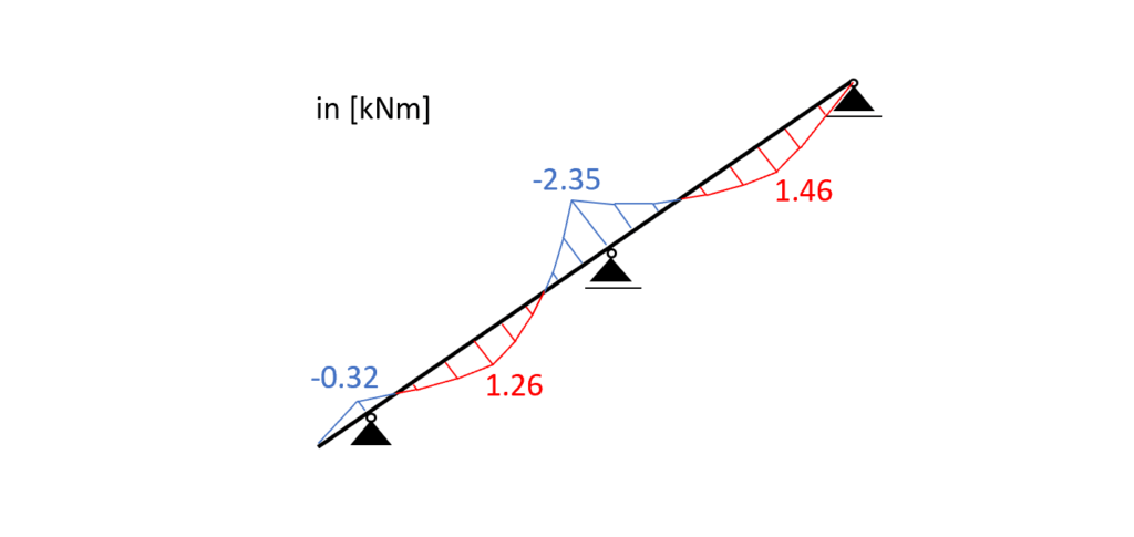
Load combination 3 – Bending moments
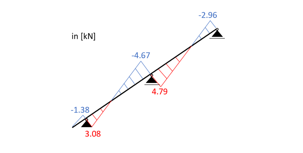
Load combination 3 – Shear forces
Load combination 3 – Normal forces
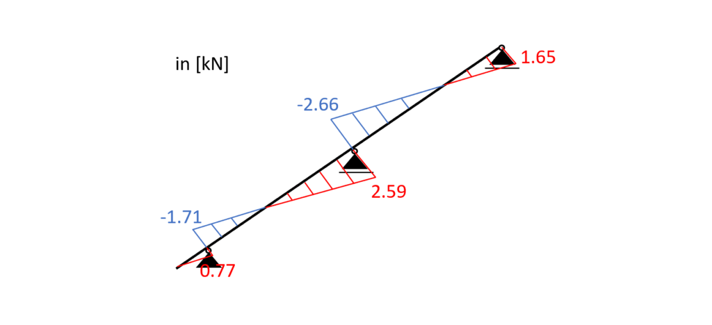
Bending and Compression
From the max. bending moment (midsupport: -2.35 kNM) and the compression force (2.66 kN) in the same point we can calculate the stress in the most critical cross section.
Bending stress:
$\sigma_{m} = \frac{M_{d}}{I_{y}} * \frac{h}{2} = \frac{2.35 kNm}{1.372*10^{-5}} * \frac{0.14m}{2} = 11.99 MPa$
Compression stress:
$\sigma_{c} = \frac{N_{d}}{w * h} = \frac{2.66 kN}{0.08m * 0.14m} = 0.317 MPa$
Resistance stresses of the timber material:
$ f_{d} = k_{mod} * \frac{f_{k}}{\gamma_{m}} $
| LC3 (L-action) | $k_{mod.L} * \frac{f_{m.k}}{\gamma_{m}} $ | $0.8 * \frac{24 MPa}{1.3} $ | $14.77 MPa $ |
| LC3 (L-action) | $k_{mod.L} * \frac{f_{c.k}}{\gamma_{m}} $ | $0.8 * \frac{21 MPa}{1.3} $ | $12.92 MPa $ |
Utilization according to EN 1995-1-1 (6.19)
$\eta = (\frac{\sigma_{c}}{f_{c.d}})^2 + \frac{\sigma_{m}}{f_{m.d}} = 0.812 < 1.0$
Bending and Tension
From the max. bending moment (midsupport: -2.35 kNM) and the tension force (2.59 kN) in the same point we can calculate the stress in the most critical cross section.
Bending stress:
$\sigma_{m} = 11.99 MPa$
Tension stress:
$\sigma_{t} = \frac{N_{d}}{w * h} = \frac{2.59 kN}{0.08m * 0.14m} = 0.308 MPa$
Resistance stresses of the timber material:
$ f_{d} = k_{mod} * \frac{f_{k}}{\gamma_{m}} $
| LC3 (L-action) | $k_{mod.L} * \frac{f_{m.k}}{\gamma_{m}} $ | $0.8 * \frac{24 MPa}{1.3} $ | $14.77 MPa $ |
| LC3 (L-action) | $k_{mod.L} * \frac{f_{t.k}}{\gamma_{m}} $ | $0.8 * \frac{14 MPa}{1.3} $ | $8.62 MPa $ |
Utilization according to EN 1995-1-1 (6.17)
$\eta = \frac{\sigma_{t}}{f_{c.d}} + \frac{\sigma_{m}}{f_{m.d}} = 0.85 < 1.0$
Shear
From the max. shear force (midsupport: 4.79 kN) we can calculate the shear stress in the most critical cross section.
Shear stress:
$\tau_{d} = \frac{3*V}{2*w*h} = \frac{3*4.79 kN}{2*0.08m*0.14m} = 0.86 MPa$
Resistance stresses of the timber material:
$ f_{v} = k_{mod.L} * \frac{f_{v}}{\gamma_{m}} $
$ f_{v} = 0.8 * \frac{4 MPa}{1.3} = 2.46 MPa$
Utilization according to EN 1995-1-1 (6.13)
$\eta = \frac{\tau_{v}}{f_{v}} = 0.35 < 1.0$
Buckling
We assume that buckling out of the plane (z-direction) can be neglected because the rafters are held on there sides. Therefore we can define the buckling length $l_{y}$ as
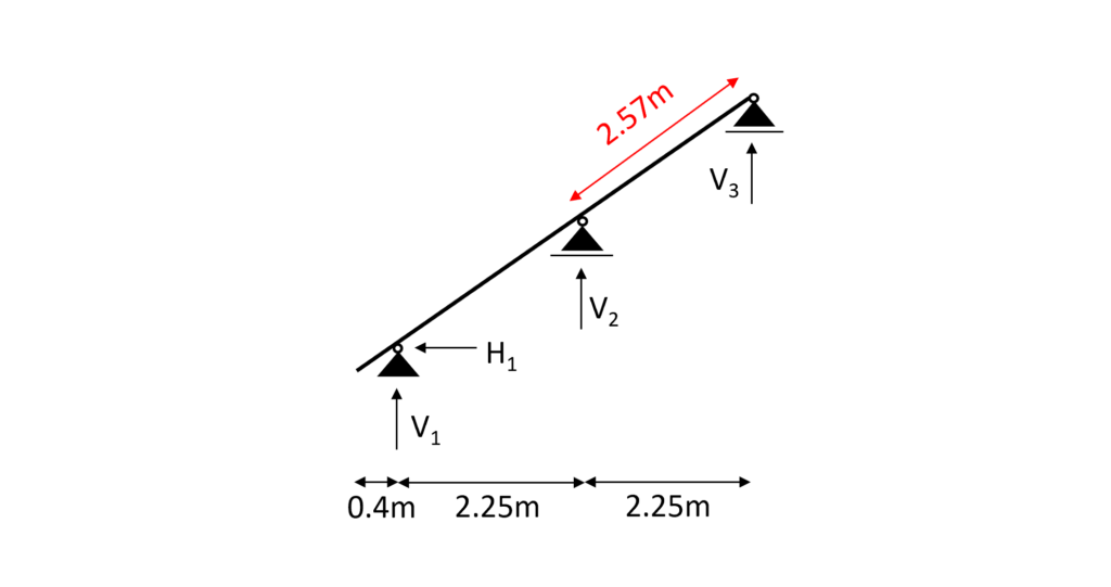
$l_{y} = 2.57 m$
Radius of inertia
$i_{y} = \sqrt{\frac{I_{y}}{w*h}} = 0.04m$
Slenderness ratio
$\lambda_{y} = \frac{l_{y}}{i_{y}} = 63.59$
Relative slenderness ratio (EN 1995-1-1 (6.21))
$ \lambda_{rel.y} = \frac{\lambda_{y}}{\pi} * \sqrt{\frac{f_{c.0.k}}{E_{0.g.05}}} = 0.957$
$\beta_{c}$ factor for solid timber (EN 1995-1-1 (6.29))
$\beta_{c} = 0.2$
Instability factor (EN 1995-1-1 (6.27))
$k_{y} = 0.5 * (1+ \beta_{c} *(\lambda_{rel.y} – 0.3) + \lambda_{rel.y}^2) = 1.023$
Buckling reduction coefficient (EN 1995-1-1 (6.25))
$k_{c.y} = \frac{1}{k_{y} + \sqrt{k_{y}^2 – \lambda_{rel.y}^2}} = 0.721$
Utilization (EN 1995-1-1 (6.23))
$\frac{\sigma_{c}}{k_{c.y} * f_{c.d}} + \frac{\sigma_{m}}{f_{m.d}} = 0.846$
💡 From the buckling calculation we can see that the axial compression force is so little compared to the bending that is has very little influence on the Utilization.
SLS Design
We also discussed the SLS design a bit more in detail in a previous article. In this blog post we are not explaining too much but rather show the calculations😊.
Instantaneous deformation $u_{inst}$
$u_{inst}$ (instantaneous deformation) of our beam can be calculated with the load of the characteristic load combination.
As for the bending moments, shear and axial forces, we are using a FE programme to calculate the deflections due to our Load combinations.
LC 3 of the characteristic SLS load combinations leads to the largest deflection u.
$u_{inst}$ = 3.3 mm
Unfortunately, EN 1995-1-1 Table 7.2 recommends values for $w_{inst} only for “Beams on two supports” and “Cantilevering beams” and not for a continuous beam, which is our case.
However, the limits of the deflection can be agreed upon with the client and the structure is not collapsing due to too large deflections if the rafter is verified for all ULS calculations.
So for the sake of this tutorial we are using the value for “Beam on two supports” from EN 1995-1-1 Table 7.2.
$w_{inst}$ = l/300 = 2.57m/300 = 8.57 mm
Utilization
$\eta = \frac{u_{inst}}{w_{inst}} = \frac{3.3mm}{8.57mm} = 0.39$
Final deformation $u_{fin}$
$u_{fin}$ (final deformation) of our beam can be calculated by adding the creep deformation $u_{creep}$ to the instantaneous deflection $u_{inst}$.
Therefore, we will calculate the creep deflection with a FE program.
This might be a bit quick, but we have already covered the basics in the article about the timber beam dimensioning.
So check that out if you want to know exactly how to calculate $u_{creep}$ by hand.
$u_{creep}$ = 0.96mm
Adding the creep to the instantaneous deflection leads to the final deflection.
$u_{fin} = u_{inst} + u_{creep} = 3.3mm + 0.96mm= 4.26mm$
Limit of $u_{fin}$ according to EN 1995-1-1 Table 7.2
$w_{fin}$ = l/150 = 2.57m/150 = 17.133 mm
Utilization
$\eta = \frac{u_{fin}}{w_{fin}} = \frac{4.26mm}{17.133mm} = 0.25$
🎉 Finishing off with the final deflection criteria, the rafter is now designed and verified. The next step is to apply the support forces to the purlins and design the purlins. So see you in the next tutorial😎.
![Tensile Capacity of Nails [Eurocode]](https://www.structuralbasics.com/wp-content/uploads/2026/01/Tensile-capacity-of-nails-768x439.png)
![Masonry Wall Subjected To Point Load [Step-By-Step Guide]](https://www.structuralbasics.com/wp-content/uploads/2024/03/Masonry-wall-subjected-to-point-load-768x439.jpg)
![What Is A Fillet Weld? [All You Need To Know]](https://www.structuralbasics.com/wp-content/uploads/2023/09/Fillet-weld-768x439.jpg)