Arch structure: Bending moment, normal and Shear force calculation due to a point load (Complete guide)
Nowadays almost every structural engineer uses FE programs to calculate bending moments, shear, axial and reaction forces and stresses.
However, those programs give us sometimes wrong results due to bugs or wrong user input from our side.
Therefore, it’s really important to check the results by hand calculations.
After starting this new series of posts with the cantilever and the simply supported beam, we continue our journey with the static system of an arch structure.
We’ll show, step-by-step, how the bending moments, normal shear and reaction forces are calculated, how the results can be visualized in moment, shear and normal force diagrams and what different static systems of the arch structure exist.
All will be shown by examples.
Not much more talk, let’s get started.
🙋♀️ What is an arch?
The arch is – statically speaking – a structure that acts mainly in compression which makes it very efficient. However, the flatter – meaning the smaller the rise to span ratio – the more bending moments it takes. The static system of the arch can have different support conditions which are explained further in the following.
We are surrounded by many arches in our daily lives.
Here are 5 examples of structural arches in real life
- Arch bridges
- Supports of a bench
- The supporting structure of a table tennis plate
- Roman Aqueducts
- Masonry arches to span over windows and doors
👆 The static system(s) of the arch structure
The arch structure has a variety of different static systems due to different support and connection conditions.
The beam element can take normal and shear forces, as well as bending moments. The following static systems are used.
Hingeless arch
The hingeless arch is categorized by having 2 fixed supports and no hinged connection. Therefore the static system is indetermined. The fixed supports (a) and (b) take up
- a vertical reaction force $V$
- a horizontal reaction force $H$ and
- a moment reaction $M$
1 Hinged arch
The 1 hinged arch is characterized by having 2 fixed supports and 1 hinged connection. Therefore, the static system is indeterminate.
As the hingeless arch, the fixed supports (a) and (b) of the 1 hinged arch take up
- a vertical reaction force $V$
- a horizontal reaction force $H$ and
- a moment reaction $M$
2 Hinged arch
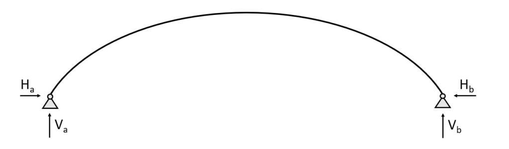
The 2 hinged arch is still statically indeterminate and characterized by having 2 pin supports and no hinged connection. The pin supports (a) and (b) of the 2 Hinged arch take up
- a vertical reaction force $V$ and
- a horizontal reaction force $H$
3 Hinged arch
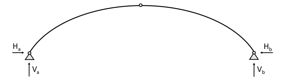
The 3 hinged arch is statically determinate and characterized by having 2 pin supports and 1 hinged connection.
Due to its statical determinacy, we can calculate the internal and reaction forces due to equilibrium conditions. The pin supports (a) and (b) of the 3 Hinged arch take up
- a vertical reaction force $V$ and
- a horizontal reaction force $H$
🏢 The static system of the arch applied on real structures
Understanding the static system of a structure is probably one of the hardest parts about statics and structural engineering in the beginning.
From my experience it’s not that often explained at university and there is very little information about it online as well, isn’t it?
So let’s look at some applied examples.
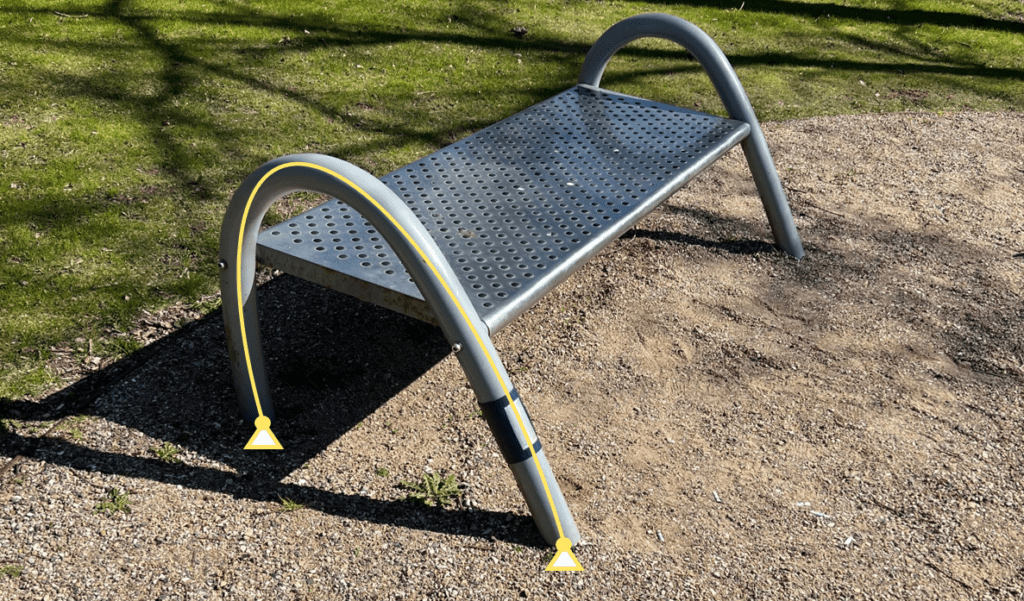
- The supporting structure of bench panels. I saw this bench while being on a walk. I don’t know about you but learning about structures makes me see only structures and static systems when being out on walks😂. Are you the same? Anyway, i interprete this supporting structure as a 2 Hinged arch because it seems to have some rotational capacity at the supports. But keep in mind that different designers might interpret it differently.
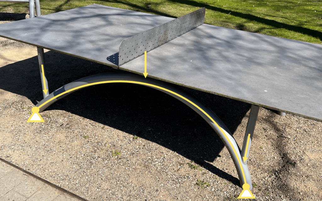
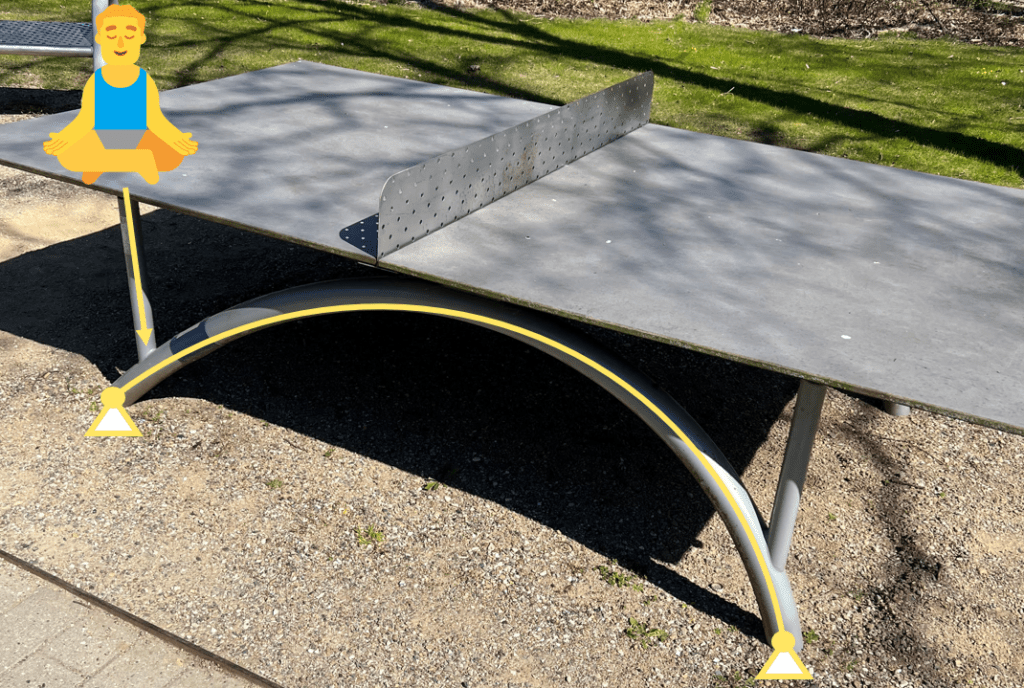
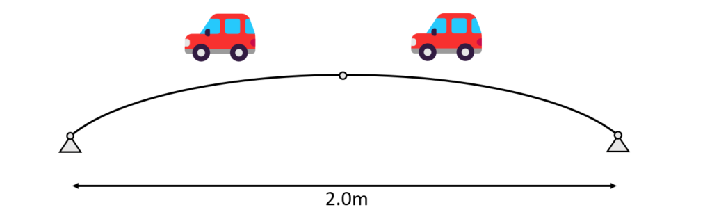
- The supporting structure of a table tennis table. On the same walk i discovered another 2 hinged arch. It can also easily be seen that all of the dead load and other loads of the top plate are transfered as Point loads to the arch.
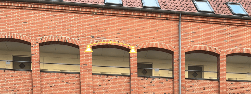
- Masonry arches are used to span over windows, doors or other openings. In the following case we see that the arch is used to transfer the weight of the wall above and other loads coming from the roof to the columns. I assume that the structural engineer used the static system of a 3 hinged arch.
⬇️ Examples of loading situations
We wanna keep it a bit joyful and realistic in this blog, right? So let’s look at loading scenarios we all can relate to.
🧍 A person sitting and meditating on the table tennis plate – A Point load
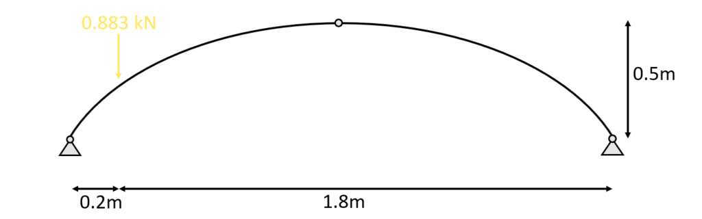
Let’s look at the example where a person sits and meditates (🧘♂️) on the table tennis plate above one of the columns which is connected to the arch.
Let’s assume that all the weight is transferred through the plate and into the column. And we assume that this person weighs 90 kg.
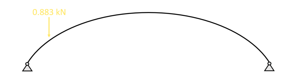
This weight of 90 kg can directly be translated into 0.883 kN.
Now because the yogi sits in a specific point with his butt, the load is concentrated and therefore the 0.883 kN equals a point load which is transferred through the column. This point load can then be applied to the arch.
🏋️ The self-weight of a wall on a masonry arch above a window – Line load
So, walls have a self-weight, right?
I guess everyone can imagine that because nobody would be able to lift a concrete or masonry wall.
In structural engineering, we also call this dead load, and it’s distributed along the shape of the structural element.
For the case of the masonry wall from the picture above, the self-weight per $m$ is calculated as
$\mbox{Density} \, \rho \cdot \mbox{Cross-sectional Area A} \,$
The density of masonry is found by googling ($\rho = 2000 \mbox{kg/m}^3$)
The cross-sectional area of the wall is calculated as
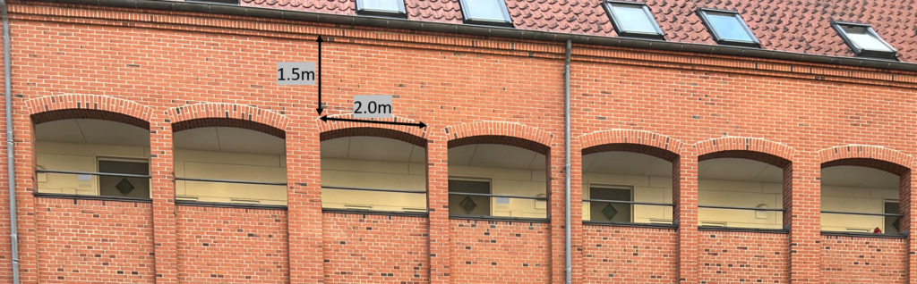
$\mbox{Height} \, h \cdot \mbox{Thickness} \, t = 1.5\mbox{m} \cdot 0.4\mbox{m} = 0.6 \mbox{m}^2$
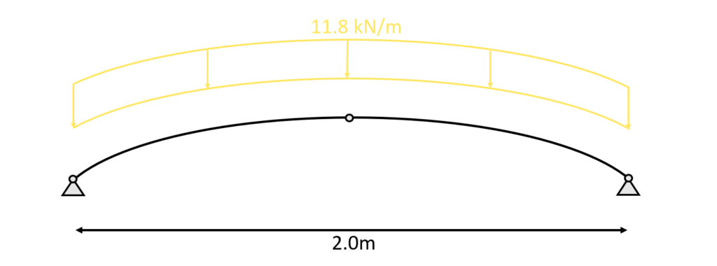
which leads to a line load of
$2000 \mbox{kg/m}^3 \cdot 0.6 \mbox{m}^2 = 11.8 \mbox{kN/m}$
Now, it always helps to translate kN in non-engineering language. $11.8$ kN/m is also, 1223 kg per $m$.
That’s roughly as much as a car – but per meter❗ So for the case of our masonry arch where we have a span of $2m$ the dead load of the wall above is equal to 2 cars🚗.
This line load (kN/m) is now also applied to the 3 hinged arch.
If you want to learn more about how to apply the different loads, then read this article.
🧮 Hand calculation of bending moment, axial and shear forces due to a point load – arch
Now in order to design the thickness and material properties of the arch of the table tennis table the forces and moments acting in the arch need to be calculated.
In general, statically determinate structures such as the cantilever, simply supported beam or the 3 hinged arch need to fullfill three equilibrium conditions:
- Horizontal equilibrium $\sum H = 0$: The sum of all horizontal loads and reactions is 0.
- Vertical equilibrium $\sum V = 0$: The sum of all vertical loads and reactions is 0.
- Moment equilibrium $\sum M = 0$: The sum of all moments is 0.
Let’s continue with the 2 loading situations that we are now familiar with – point and line load.
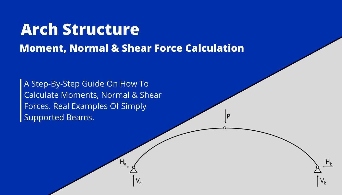
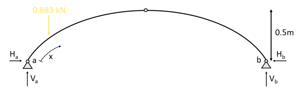
1. The first thing we always calculate in determinate structures are the reaction forces/moment. In our case that is $V_a, H_a$ at support (a) and $V_b$ at support (b) due to the equilibrium conditions.
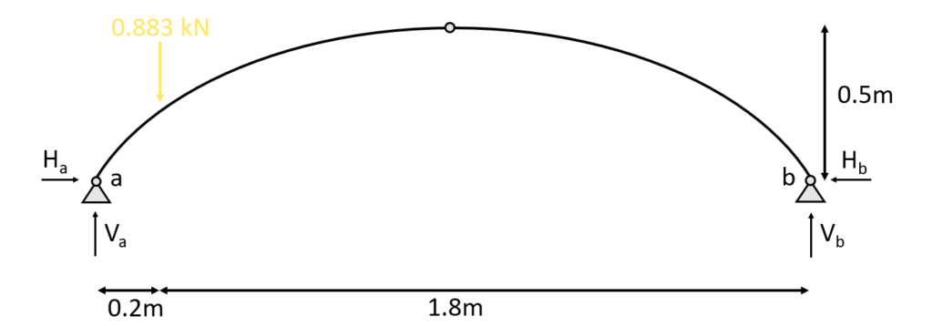
Since we don’t have a symmetric loading we can’t assume that the reaction forces at (a) and (b) are the same. We do therefore moment equilibrium in point (b).
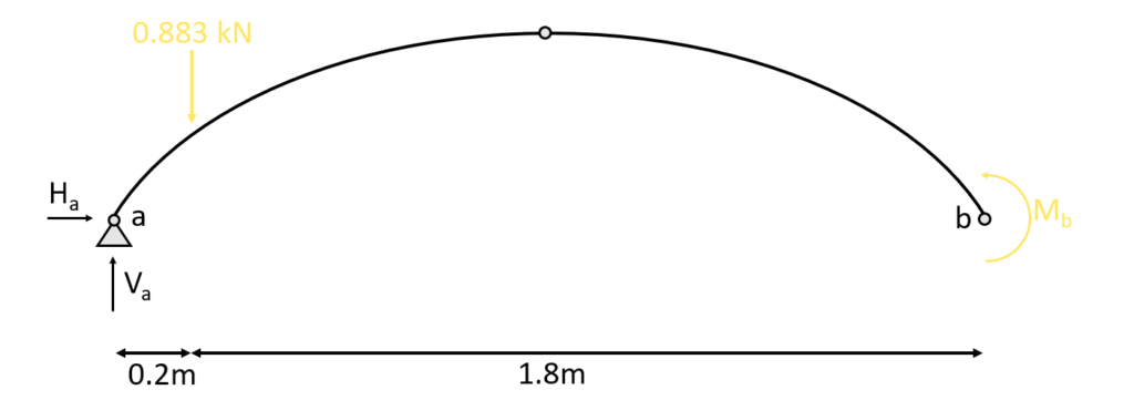
$\sum M = 0: M_b – V_a \cdot 2m + 0.883kN \cdot 1.8m = 0$
We can now derive $V_a$, since the Moment = 0 in a pin support.
$V_a = 0.883kN \cdot \frac{1.8m}{2.0m} = 0.79 kN$
From here we find $V_b$ from the vertical equilibrium as
$\sum V = 0: V_a + V_b – 0.883kN = 0$ –> $V_b = 0.883kN – 0.79kN = 0.093kN$
To find the horizontal reaction forces we do moment equilibrium in the top hinge.
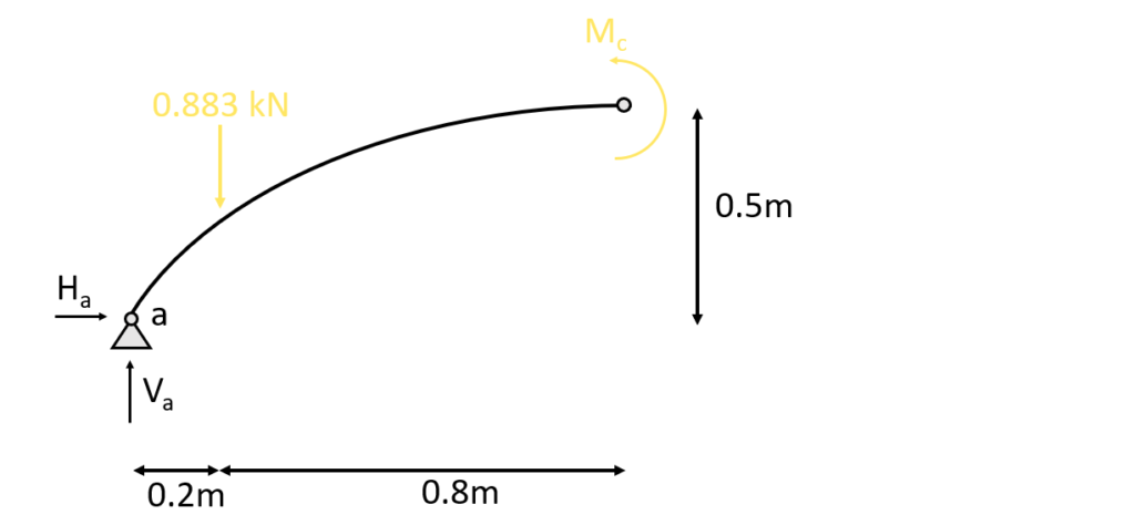
$\sum M = 0: M_c – V_a \cdot 1m + 0.883kN \cdot 0.8m + H_a \cdot 0.5m = 0$
We can now derive $H_a$, since the Moment = 0 is a hinged connection.
$H_a = 0.79kN \cdot \frac{1.0m}{0.5m} – 0.883kN \cdot \frac{0.8m}{0.5m}= 0.17 kN$
From here we find $H_b$ from the horizontal equilibrium as
$\sum H = 0: H_a – H_b = 0$ –> $H_b = 0.17kN$
2. Calculation of the shear, normal and moment distribution along the arch due to the reaction forces. The parameter x is introduced as the length between point a and any point on the arch.
There is 2 ways to calculate the length of the arch
- by mathematical formulas or
- by a CAD program
We choose the second option because it speeds up things a little bit.
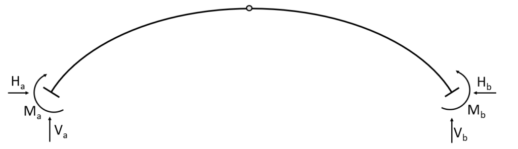
3. The shear forces and bending moments can be calculated in dependence of x and the angle $\alpha$ which can be seen in the next picture. Let’s make a first cut at a point between the support (a) and the point load 0<x<0.291m. As already mentioned the dimension 0.291 is calculated in a CAD program.
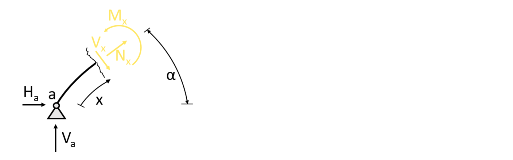
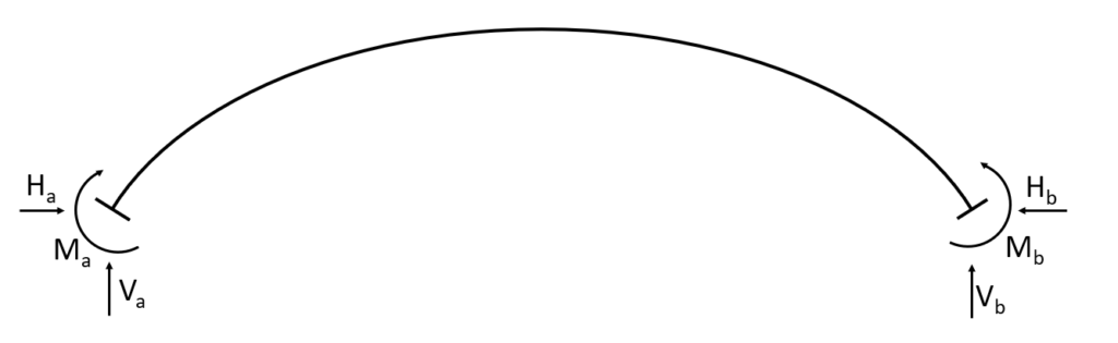
As for the reaction force calculation, the equilibrium conditions are used to calculate the moment and shear forces at point x but this time not in the horizontal or vertical direction but rather in the normal and shear force directions.
This means that we split up the reaction forces in the normal and shear force direction.
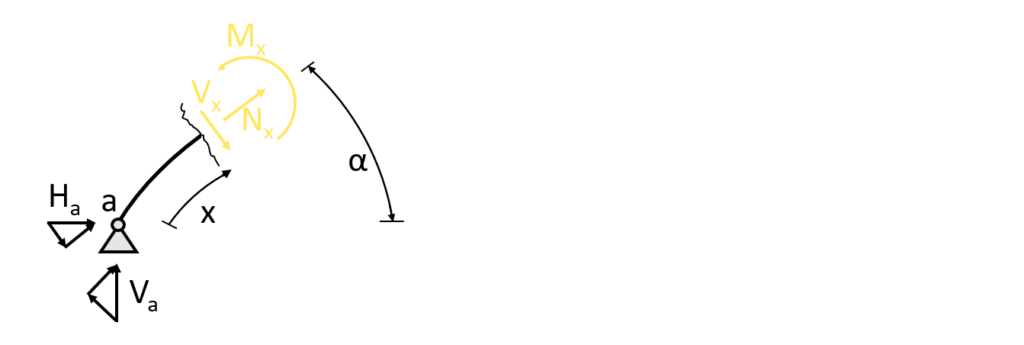
$\sum N = 0: N_x + H_a \cdot cos(\alpha) + V_a \cdot sin(\alpha) = 0$
$N_x = -H_a \cdot cos(\alpha) – V_a \cdot sin(\alpha) = -0.17kN \cdot cos(\alpha) – 0.79kN \cdot sin(\alpha)$
$\sum V = 0: -H_a \cdot sin(\alpha) + V_a \cdot cos(\alpha) – V_x = 0$
$V_x = -H_a \cdot sin(\alpha) + V_a \cdot cos(\alpha) = -0.17kN \cdot sin(\alpha) + 0.79kN \cdot cos(\alpha) $
For the bending moment calculation it’s easier to use the horizontal and vertical distances which we call $x_{hor}$ and $x_{vert}$.
$\sum M = 0: M_x – V_a \cdot x_{hor} + H_a \cdot x_{vert} = 0$
$M_x = V_a \cdot x_{hor} – H_a \cdot x_{vert} = 0.79kN \cdot x_{hor} – 0.17kN \cdot x_{vert}$
Let’s do a first calculation for one specific point at x = 145mm. From a CAD program we get the other dimensions $\alpha = 49.8°$, $x_{hor} = 93.9mm$ and $x_{vert} = 111mm$. The internal forces are now calculated as
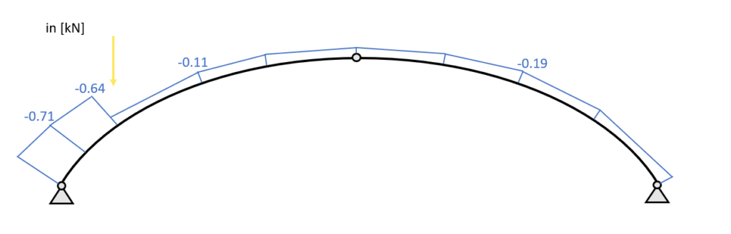
$N_{145mm} = -0.17kN \cdot cos(49.8°) – 0.79kN \cdot sin(49.8°) = -0.713 kN$
$V_{145mm} = -0.17kN \cdot sin(49.8°) + 0.79kN \cdot cos(49.8°) = 0.38 kN$
$M_{145mm} = 0.79kN \cdot 93.9mm – 0.17kN \cdot 111mm = 0.055 \mbox{kNm}$
Now let’s do the same for the point where the point load is applied. We have the following parameters
- $x = 291mm$
- $\alpha = 40°$
- $x_{hor} = 200mm$
- $x_{vert} = 210.47mm$
The good thing here – we can use the exact same formula. Just with different values.
$N_{291mm} = -0.17kN \cdot cos(40°) – 0.79kN \cdot sin(40°) = -0.64 kN$
$V_{291mm} = -0.17kN \cdot sin(40°) + 0.79kN \cdot cos(40°) = 0.5 kN$
$M_{291mm} = 0.79kN \cdot 200mm – 0.17kN \cdot 210.5mm = 0.122 \mbox{kNm}$
4. Cut at a point between the point load and the hinge connection 0.291m<x<1.159m
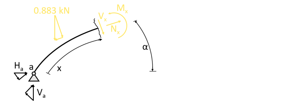
We basically end up with the same equilibrium conditions except that now the Point load is included.
$\sum N = 0: N_x + H_a \cdot cos(\alpha) + V_a \cdot sin(\alpha) – 0.883kN \cdot sin(\alpha)= 0$
$N_x = -H_a \cdot cos(\alpha) – V_a \cdot sin(\alpha) + 0.883kN \cdot sin(\alpha) = -0.17kN \cdot cos(\alpha) – 0.79kN \cdot sin(\alpha) + 0.883kN \cdot sin(\alpha)$
$\sum V = 0: -H_a \cdot sin(\alpha) + V_a \cdot cos(\alpha) – V_x – 0.883kN \cdot cos(\alpha) = 0$
$V_x = -H_a \cdot sin(\alpha) + V_a \cdot cos(\alpha) – 0.883kN \cdot cos(\alpha) = -0.17kN \cdot sin(\alpha) + 0.79kN \cdot cos(\alpha) – 0.883kN \cdot cos(\alpha) $
$\sum M = 0: M_x – V_a \cdot x_{hor} + H_a \cdot x_{vert} + 0.883kN \cdot (x_{hor} – 0.2m)= 0$
$M_x = V_a \cdot x_{hor} – H_a \cdot x_{vert} – 0.883kN \cdot (x_{hor} – 0.2m)= 0.79kN \cdot x_{hor} – 0.17kN \cdot x_{vert} – 0.883kN \cdot (x_{hor} – 0.2m)$
Let’s do the calculation for one specific point which has the dimension parameters
- $x = 579.5mm$
- $\alpha = 26.59°$
- $x_{hor} = 441mm$
- $x_{vert} = 368mm$
$N_{579.5mm} = -0.17kN \cdot cos(26.6°) – 0.79kN \cdot sin(26.6°) + 0.883kN \cdot sin(26.6°) = -0.11 kN$
$V_{579.5mm} = -0.17kN \cdot sin(26.6°) + 0.79kN \cdot cos(26.6°) – 0.883kN \cdot cos(26.6°) = -0.16 kN$
$M_{291mm} = 0.79kN \cdot 441mm – 0.17kN \cdot 368mm – 0.883kN \cdot (441mm – 200mm) = 0.073 \mbox{kNm}$
We could do one more at the hinge connection, but in order to keep it a bit shorter we skip it and continue with the last section of formulas – finally.
5. Cut at a point between the point load and the hinge connection 2318mm<x<1159mm
Basically, we mirror the cut and the formulas from the first equilibrium we did at the z axis and just use different reaction forces.
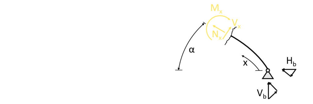
$\sum N = 0: N_x + H_b \cdot cos(\alpha) + V_b \cdot sin(\alpha) = 0$
$N_x = -H_b \cdot cos(\alpha) – V_b \cdot sin(\alpha) = -0.17kN \cdot cos(\alpha) – 0.09kN \cdot sin(\alpha)$
$\sum V = 0: H_b \cdot sin(\alpha) – V_b \cdot cos(\alpha) – V_x = 0$
$V_x = H_b \cdot sin(\alpha) – V_b \cdot cos(\alpha) = 0.17kN \cdot sin(\alpha) – 0.09kN \cdot cos(\alpha) $
For the bending moment calculation it’s easier to use the horizontal and vertical distances which we call $x_{hor}$ and $x_{vert}$.
$\sum M = 0: M_x – V_b \cdot x_{hor} + H_b \cdot x_{vert} = 0$
$M_x = V_b \cdot x_{hor} – H_b \cdot x_{vert} = 0.09kN \cdot x_{hor} – 0.17kN \cdot x_{vert}$
Let’s do the calculation for one specific point which has the dimension parameters
- $x = 579.5mm$
- $\alpha = 26.59°$
- $x_{hor} = 441mm$
- $x_{vert} = 368mm$
$N_{579.5mm} = -0.17kN \cdot cos(26.6°) – 0.09kN \cdot sin(26.6°) = -0.19 kN$
$V_{579.5mm} = 0.17kN \cdot sin(26.6°) – 0.09kN \cdot cos(26.6°) = -0.004 kN$
$M_{579.5mm} = 0.09kN \cdot 441mm – 0.17kN \cdot 368mm = -0.023 \mbox{kNm}$
Now we could do much more of those parameters and the more we do, the more accurate the internal force diagrams would look.
👨🏫 Bending moment, normal and shear force diagrams – Arch with Point load
The diagrams can be plotted by a tool like Excel using the formulas from above or drawn by hand when one is aware of the geometrical shape of the distribution.
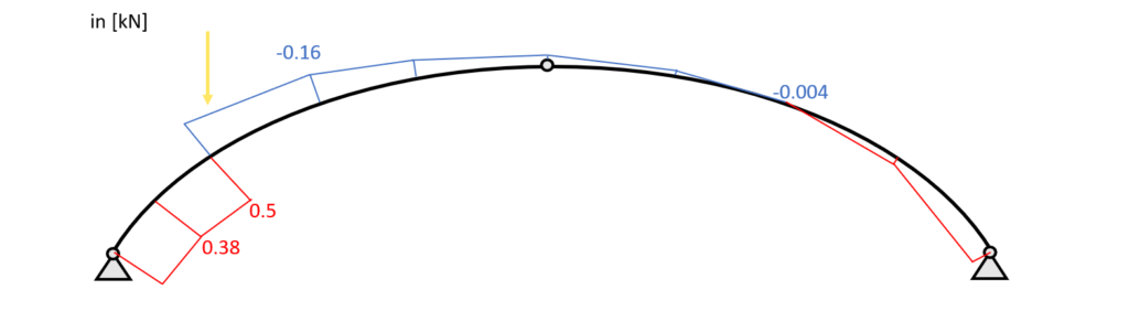
Normal force diagram – Point load – Arch
Shear force diagram – Point load – Arch
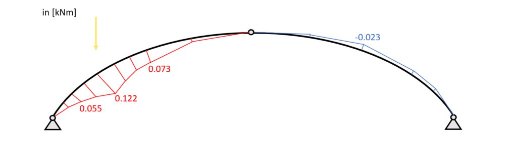
Bending moment diagram – Point load – Arch
🔎 Conclusion
Now in this blog post we only covered the moments, shear and normal forces due to a point load. However, there are also uniformly distributed loads which can be applied on the arch in different ways.
Those loads are
Once the internal forces due to those loads are calculated, the results are combined in load combinations and the design of the element can be done. In our case, that is the concrete and rebar design of the arch.
Now I would like to hear from you: What arch structures have you already seen in real life? Let us know in the comments below📝
![Gambrel Truss [A Structural Guide]](https://www.structuralbasics.com/wp-content/uploads/2023/02/Gambrel-truss-768x439.jpg)