How To Calculate The Wind Loads Of A Flat Roof [2026]
Wind loads need to be considered in the structural calculation of every building and structure.
In this article, you are going to learn, step-by-step, how to calculate the wind load on flat roofs according to EN 1991-1-4.
The calculation of the wind load is split up in multiple articles due to the fact that the wind load depends on a lot of parameters and because the wind load is calculated differently for walls, roofs and arches.
The wind load on flat roofs and this article are based on the peak velocity pressure.
Alright, let’s get started. 🚀🚀
Step-By-Step Process Of Calculating The Wind Loads On Flat Roofs
In order to calculate the wind load or wind pressure on external surfaces of the flat roof, we are going to do the following steps:
- Calculate the wind velocity pressure qp
- Define the outer geometry of the building
- Calculate the width of the Wind areas
- Find the external pressure coefficients
- Calculate the wind pressures/loads
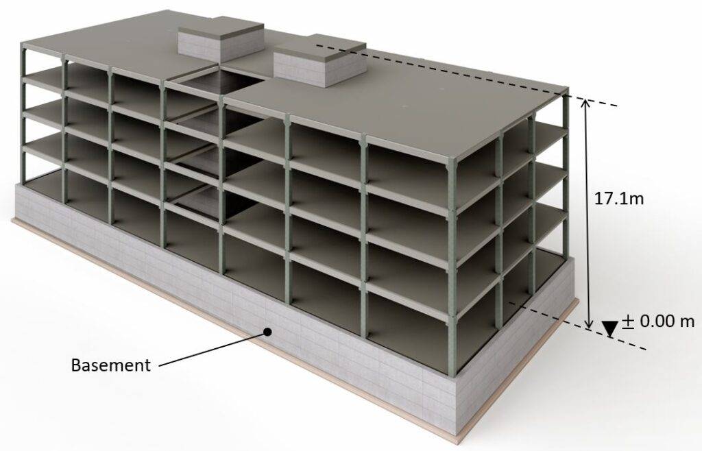
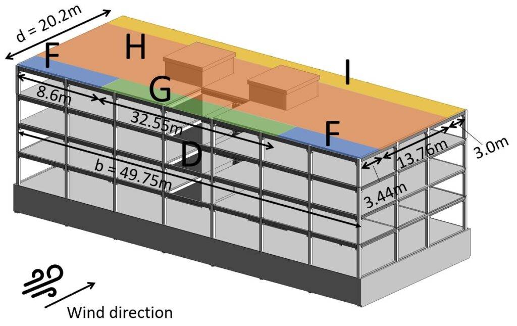
Example Building
We’ll use the following example building to show all the steps of calculating the wind load on flat roofs.
Geometry And Parameters From Wind Velocity Pressure
This is a quick summary of the values we calculated to get the wind velocity pressure.
| Fundamental value of basic wind velocity | $v_{b.0}$ | $24 \frac{m}{s} $ |
| Orography factor | $c_{0} $ | $1.0 $ |
| Turbulence factor | $k_{l} $ | $1.0 $ |
| Density of air | $\rho$ | $1.25 \frac{kg}{m^3} $ |
| Reference height of Terrain cat. II | $z_{0.II}$ | $0.05 m$ |
| Roughness Length (Terrain cat. III) | $z_{0}$ | $0.3 m$ |
| Terrain factor | $k_{r}$ | $0.215$ |
| Turbulance Intensity | $I_{v}$ | $0.247$ |
| Roughness factor | $c_{r}$ | $0.871$ |
| Mean wind velocity | $v_{m}$ | $20.9 \frac{m}{s} $ |
| Peak velocity pressure | $q_{p}$ | $0.746 \frac{kN}{m^2}$ |
Wind Pressure On Surfaces
Eurocode (EN 1991-1-4:2005) distinguishes in general between wind pressure on external and internal surfaces. This article is focusing on the wind pressure on external surfaces.
Wind pressure on external surfaces we
The formula (EN 1991-1-4:2005 (5.1)) to calculate the wind pressure on external surfaces is
$$w_{e} = q_{p} \cdot c_{pe}$$
Where
| qp | is the peak velocity pressure and |
| cpe | is the external pressure coefficient |
The coefficient cpe has 2 different values depending on the wind loaded area. There is a value for a surface area of 1 m2 and 10 m2. These two values can also be written as
| cpe.1 | for the external pressure coefficient for an area of 1 $ m^2$ and |
| cpe.10 | for the external pressure coefficient for an area of 10 $ m^2$ |
We explained it already a bit more detailed here. If you want to a more detailed explanation then either go to the article or read up in EN 1991-1-4:2005 7.2.
EN 1991-1-4 Table 7.2 gives recommendations for cpe.10 and cpe.1.
❗This means that you have to double-check with your National annex because those values might be defined differently there❗
Table 7.2 gives values for 4 different areas F, G, H and I of our building.
Those areas depend on where the wind comes from and can be seen in EN 1991-1-4:2005 Table 7.2. For our office building, we can define the areas as
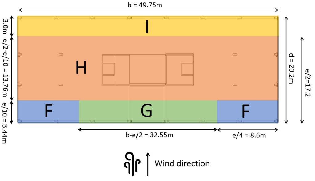
Wind from Front
| Width of building | b | 49.75 m |
| Length of building | d | 20.2 m |
| Height of building | h | 17.1m |
From those dimensions we can define e which determines the widths and depths of Areas F, G and H according to EN 1991-1-4:2005 Figure 7.6.
$$e = min(b, 2h)$$
$$e = min(49.75m, 2 \cdot 17.1m=34.4m) = 34.4m$$
From e we get the dimensions of the areas according to EN 1991-1-4:2005 Figure 7.6.
| Area | Width | Depth |
| F | e/4 = 8.6m | e/10 = 3.44m |
| G | b-e/2 = 32.55m | e/10 = 3.44m |
| H | b = 49.75m | e/2 – e/10 = 13.76m |
| I | b = 49.75m | d-e/2 = 3.0m |
So many numbers – I know. Let’s visualize them.
Okay, now let’s go back to the formula for the wind pressure for external surfaces and derive the values. The peak velocity pressure was calculated as:
$$q_{p} = 0.746 \frac{kN}{m^2}$$
Now, the external pressure coefficient also depends on the roof type. The following roof types are included:
- Sharp eaves
- With parapets
- Curved eaves and
- Mansard eaves
For the roof type of parapet with the parapet height $h_{p}$
$$h_{p} = 50cm$$
we calculate
$$h_{p}/h = 0.5m/17.1m = 0.03$$
to then look up the external pressure coefficients for our areas.
The external pressure coefficients for rectangular buildings can be taken from EN 1991-1-4:2005 Table 7.2.
| Area | cpe.10 | cpe.1 |
| Area F | -1.6 | -2.2 |
| Area G | -1.1 | -1.8 |
| Area H | -0.7 | -1.2 |
| Area I | -/+ 0.2 | -/+ 0.2 |
Don’t be confused by the + and – of the coefficients of Area I. EN 1991-1-4:2005 Table 7.2 Note 3 says that in Area I both positive and negative value should be considered.
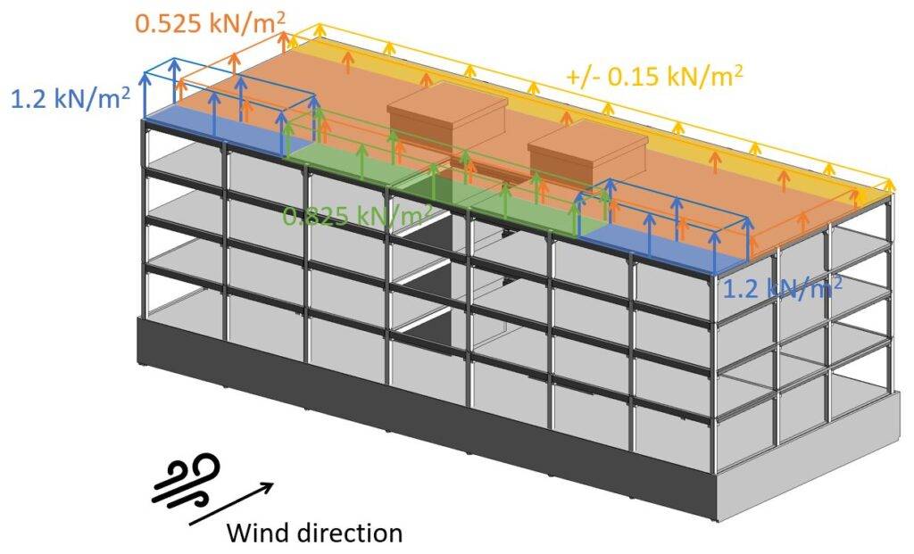
Based on our coefficients, we can now calculate the wind pressure on external surfaces.
| Area | we.10 | we.1 |
| Area F | $-1.6 \cdot 0.75 \frac{kN}{m^2} = -1.2 \frac{kN}{m^2} $ | $-2.2 \cdot 0.75 \frac{kN}{m^2} = -1.65 \frac{kN}{m^2}$ |
| Area G | $-1.1 \cdot 0.75 \frac{kN}{m^2} = -0.825 \frac{kN}{m^2} $ | $-1.8 \cdot 0.75 \frac{kN}{m^2} = -1.35 \frac{kN}{m^2}$ |
| Area H | $-0.7 \cdot 0.75 \frac{kN}{m^2} = 0.525 \frac{kN}{m^2} $ | $-1.2 \cdot 0.75 \frac{kN}{m^2} = -0.9 \frac{kN}{m^2}$ |
| Area I | $-/+0.2 \cdot 0.75 \frac{kN}{m^2} = -/+0.15 \frac{kN}{m^2} $ | $-/+0.2 \cdot 0.75 \frac{kN}{m^2} = -/+0.15 \frac{kN}{m^2}$ |
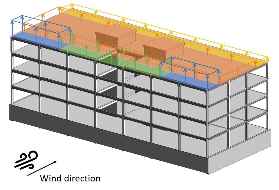
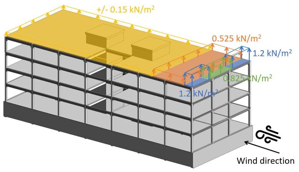
When you calculate the wind loads the first time ever, it might be very confusing in which direction you have to apply the loads. So let’s apply the wind loads with the cpe.10 coefficient (for 10 m2) on our building.
Now we also have to do the same for the case that wind comes from the side.
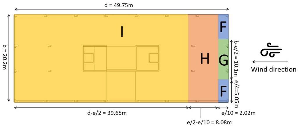
Wind from Side
In the scenario that wind comes from the side, we have to define the Area widths again. We have to redefine the geometry parameters.
| Width of building | b | 20.2 m |
| Length of building | d | 49.75 m |
| Height of building | h | 17.1 m |
From those dimensions we can define $e$ which determines the widths and depths of Areas F, G and H according to EN 1991-1-4:2005 Figure 7.6
$$e = min(b, 2h)$$
$$e = min(49.75m, 2 \cdot 17.1m=34.4m) = 20.2m$$
From e we get the dimensions of the areas according to EN 1991-1-4:2005 Figure 7.6.
| Area | Width | Depth |
| F | e/4 = 5.05m | e/10 = 2.02m |
| G | b-e/2 = 10.1m | e/10 = 2.02m |
| H | b = 20.2m | e/2 – e/10 = 8.08m |
| I | b = 20.2m | d-e/2 = 39.65m |
As we all know, a picture tells more than a thousand words – so let’s visualize all of those numbers.
For the roof type of parapet with the parapet height ratio $h_{p}/h = 0.03$ we can look up the external pressure coefficients for rectangular buildings in EN 1991-1-4:2005 Table 7.2.
| Area | cpe.10 | cpe.1 |
| Area F | -1.6 | -2.2 |
| Area G | -1.1 | -1.8 |
| Area H | -0.7 | -1.2 |
| Area I | -/+ 0.2 | -/+ 0.2 |
Based on our coefficients, we can now calculate the Wind pressure on external surfaces.
| Area | we.10 | we.1 |
| Area F | $-1.6 \cdot 0.75 \frac{kN}{m^2} = -1.2 \frac{kN}{m^2} $ | $-2.2 \cdot 0.75 \frac{kN}{m^2} = -1.65 \frac{kN}{m^2}$ |
| Area G | $-1.1 \cdot 0.75 \frac{kN}{m^2} = -0.825 \frac{kN}{m^2} $ | $-1.8 \cdot 0.75 \frac{kN}{m^2} = -1.35 \frac{kN}{m^2}$ |
| Area H | $-0.7 \cdot 0.75 \frac{kN}{m^2} = 0.525 \frac{kN}{m^2} $ | $-1.2 \cdot 0.75 \frac{kN}{m^2} = -0.9 \frac{kN}{m^2}$ |
| Area I | $-/+0.2 \cdot 0.75 \frac{kN}{m^2} = -/+0.15 \frac{kN}{m^2} $ | $-/+0.2 \cdot 0.75 \frac{kN}{m^2} = -/+0.15 \frac{kN}{m^2}$ |
Those wind area loads we can now visualize.
Conclusion
For a building of 17.1m height, located in Copenhagen, Denmark, the wind load of the flat roof is calculated for 2 directions for 4 different wind areas.
If you want to learn how to calculate the wind load on walls and pitched roofs, then check out the articles:

![Vertical Load Transfer In Structural Engineering [2026]](https://www.structuralbasics.com/wp-content/uploads/2024/09/Vertical-load-transfer-1-768x439.jpg)
![Horizontal Load Transfer In Structural Engineering [2026]](https://www.structuralbasics.com/wp-content/uploads/2024/09/Horizontal-load-transfer-768x439.jpg)