Vertical Load Transfer In Structural Engineering [2026]
When we structural engineers, design a building our job is basically to transfer the vertical loads from the roof and slabs through the building (through beams, columns, frames, trusses, etc.) down to the foundation/soil and making sure that the structural elements resist these loads.
In this article, you’ll learn how the area load applied on a slab becomes a line load which acts on a beam and how this line load then turns into a point load on top of a column.
We’ll run through #5 different examples because of the complexity of the topic.
Let’s get into it. 🚀🚀
Step-By-Step Process To Transfer Loads From The Roof To The Foundations
Here’s the step-by-step process I always follow when transferring vertical loads through a building:
Step #1: Defining the static systems of the structural elements (slabs, beams, columns, etc.)
Step #2: Applying the vertical loads like snow, dead, live load to the structural elements they act on
Step #3: Load transfer from top to bottom using the static systems
The Complexity Of Vertical Load Transfer
As simple as it sounds, transferring vertical loads through a building not that easy. In most structural engineering degrees, we are not taught how to design structural systems like buildings, warehouses, parking garages. We mostly just learn how to design a reinforced concrete beam, a timber glulam frame or steel connections. The static system and loads are given.
But how do you actually pick the right static system? Should I use a simply supported beam, or a continuous beam? Should the connection be a hinge or momentstiff?
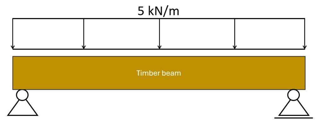
Where does this line load of 5 kN/m on the beam actually come from? And what happens with the reaction forces?
To design a building, a canopy or a warehouse, we need to understand how vertical loads travel through a structure from the roof to the foundation, from one structural element to the next.
Vertical load transfer is a very complex topic, and you need years of experience to master it. Every material works a bit differently, the type of connection determines what forces are transferred to the next element. There are endless examples.
- A hinge connection between beam and column will only transfer vertical loads to the column (and horizontal if a horizontal load acts in the beam).
- But a momentstiff connection will suddenly also transfer moments. Instead of using beam and column as the static system, we should use a frame to calculate the internal forces.
We’ll run through #5 different examples in this article, because of the complexity of the topic.
Let’s go..
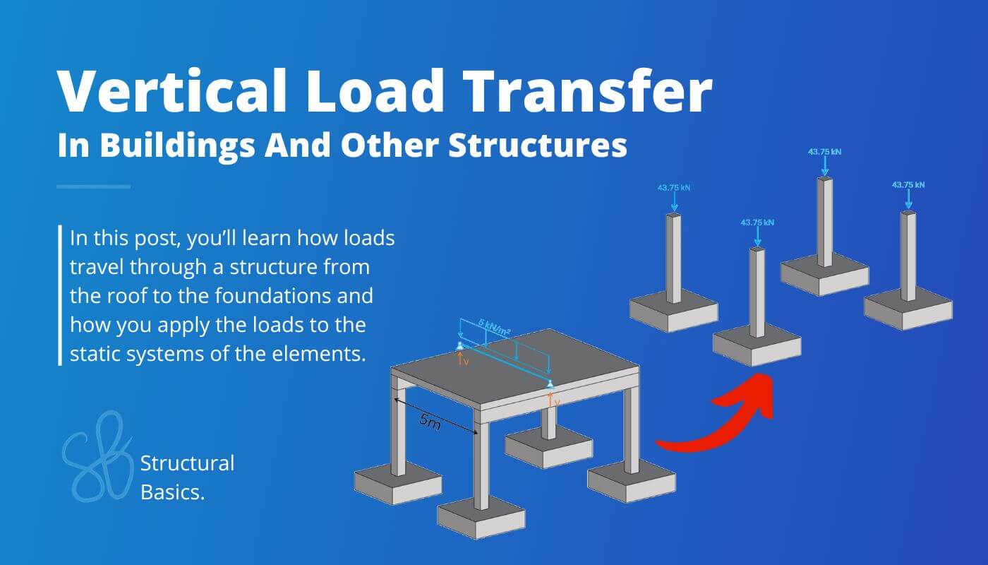
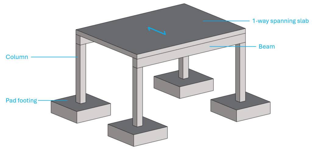
Example #1: Basic Structure To Understand Load Transfer From Slabs To Beams And To Columns
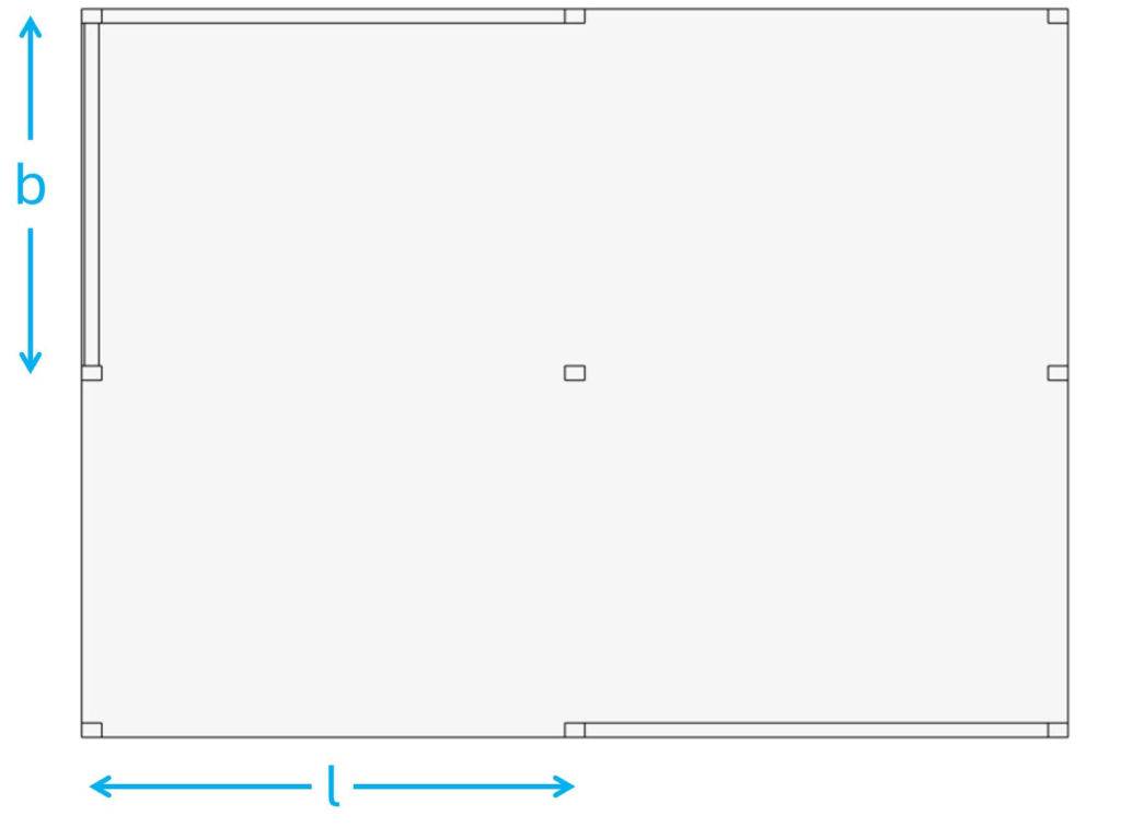
Let’s start with a basic structure consisting of a 1-way spanning slab, beams, columns and pad footings.
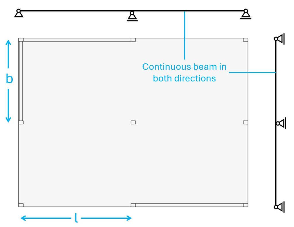
Step #1: Static systems of the structural elements
Without knowing the static systems of the structural elements, we can’t transfer the loads through the elements correctly.
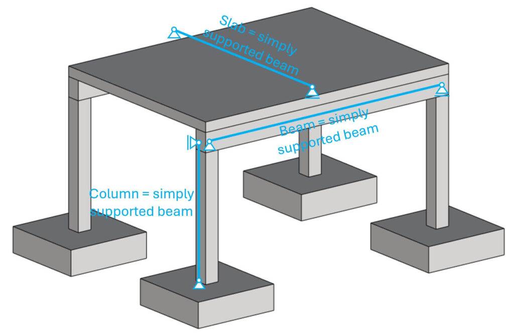
The easiest static system you can pick is the simply supported beam in terms of vertical load transfer. Note that you can’t use a simply supported beam for every structural element. Precast hollow core slabs are examples of simply supported beams, but in-situ slabs, supported by columns, beams and walls can’t be modelled as simply supported beams.
Please be also aware that the structure above is instable. It’s missing stabilizing elements like wind braces or shear walls. But that’s the topic of next week. The structure above works perfectly fine as an introduction to vertical load transfer.
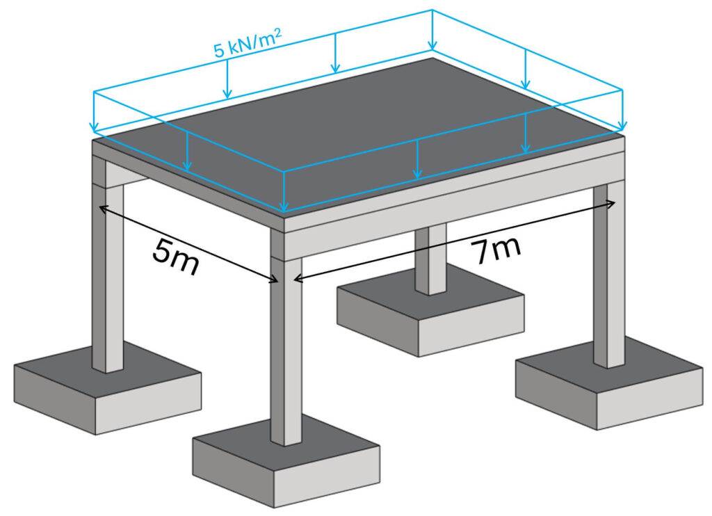
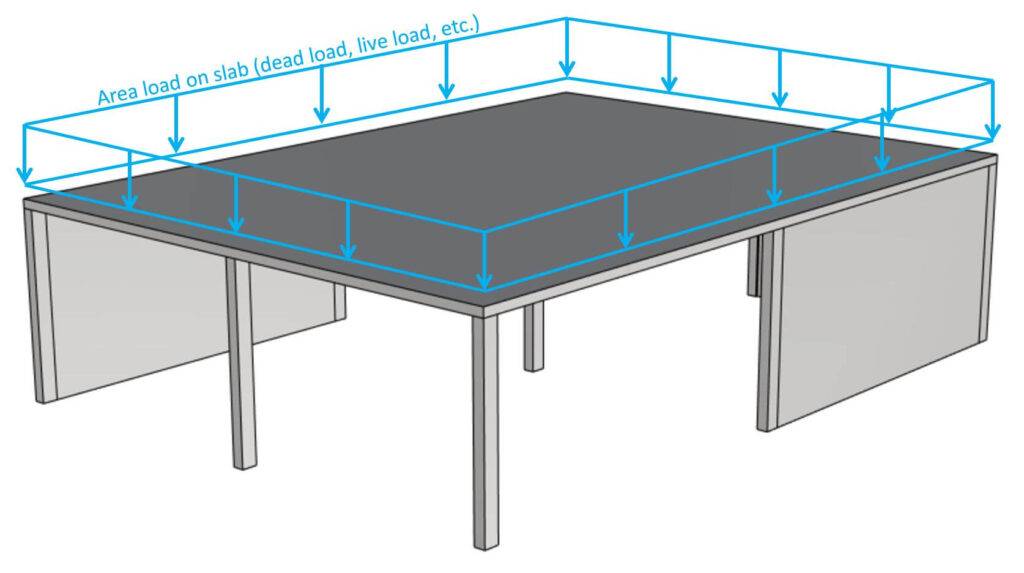
Step #2: Apply the vertical loads
Let’s say the design load on the slab is 5 kN/m2.
Step #3: Load transfer from top to bottom using the static systems
We apply the load to the static system and calculate the reaction forces. These reaction forces are then applied to the next structural element. We then again calculate the reaction forces of that element and apply it to the element that supports it.
The area load of 5 kN/m2 is applied to the slab, and we’ll calculate the reaction forces.
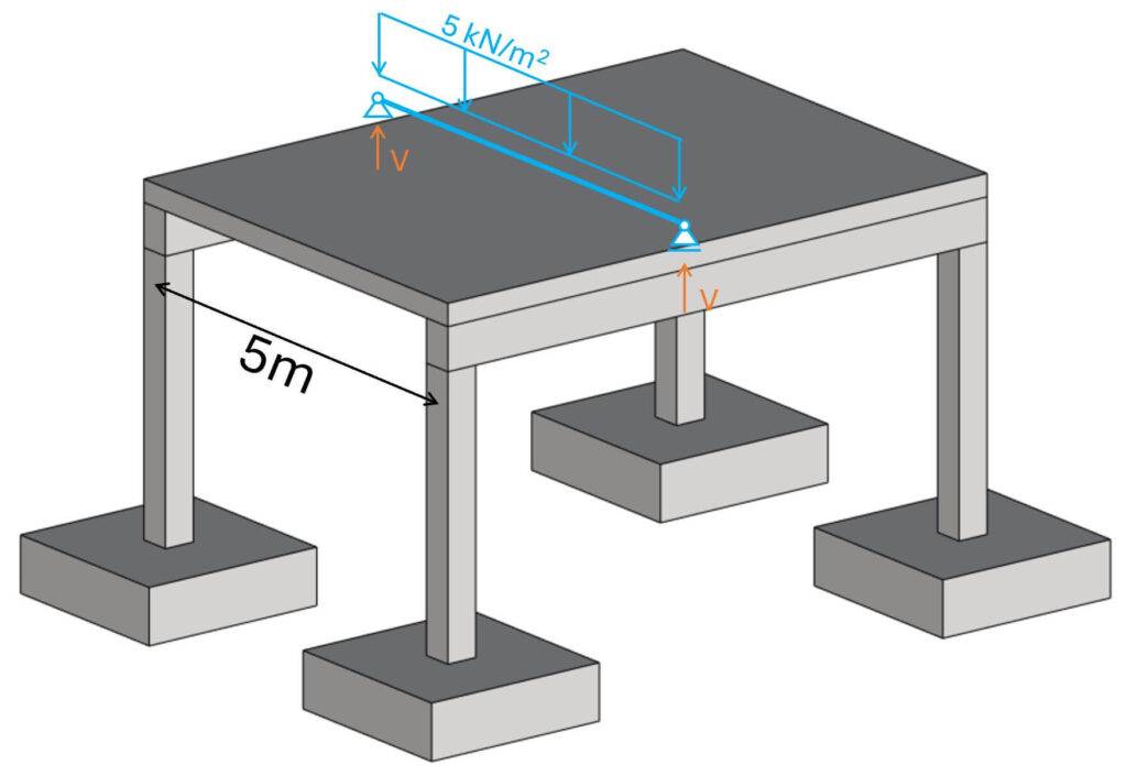
The reaction forces of the simply supported slab are calculated as:
$$V = 5 kN/m^2 \cdot 5m/2 = 12.5 kN/m$$
You can find all simply supported beam formulas → here ←.
Next, we’ll apply the reaction forces to the element that supports the slabs, the beam.
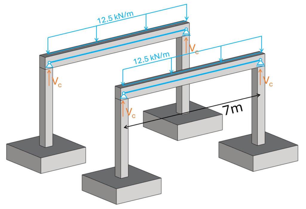
The reaction forces of the beams are calculated as:
$$V_c = 12.5 kN/m \cdot 7m/2 = 43.75 kN$$
Now, Vc is applied to the column and the pad footing.
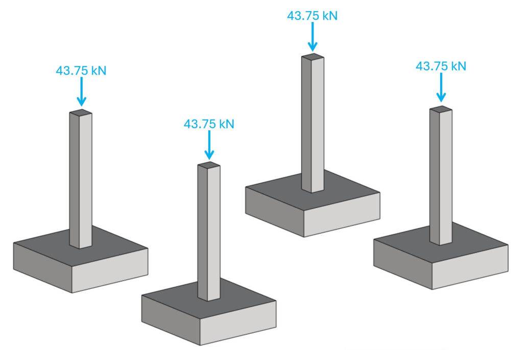
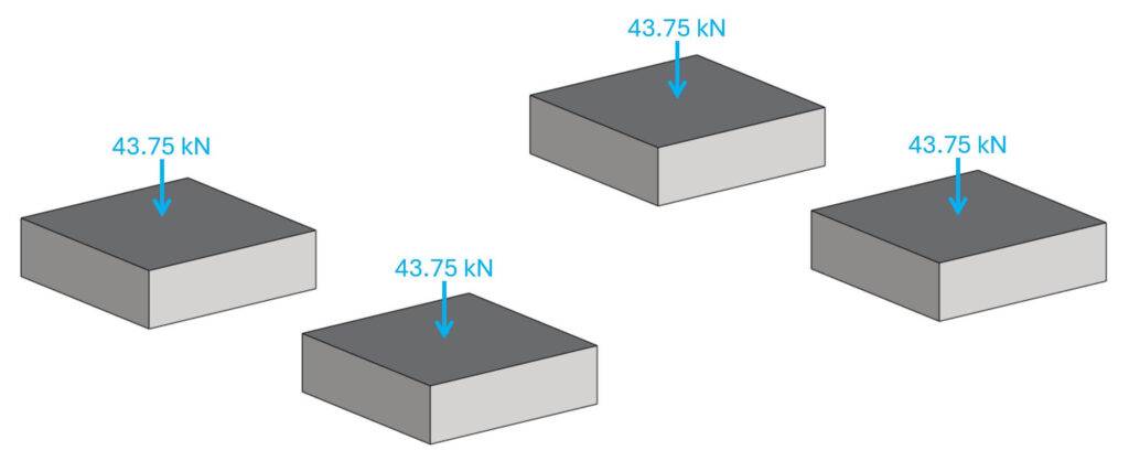
Now, you can go ahead and verify the pad footing for its geotechnical properties and design the reinforcement/concrete.
Example #2: Carport
The next example is a carport that consists of roofing, timber beams and columns.
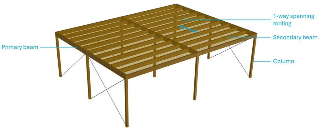
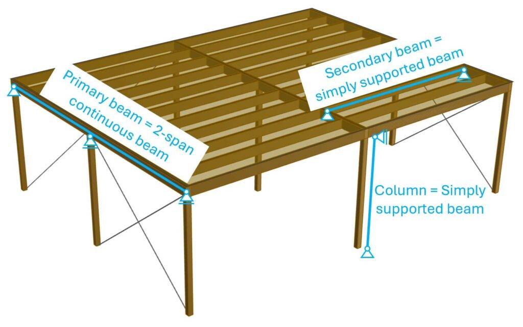
Step #1: Static systems of the structural elements
Let’s draw up the static systems again. Btw, timber columns and beams are in most designs simply supported.
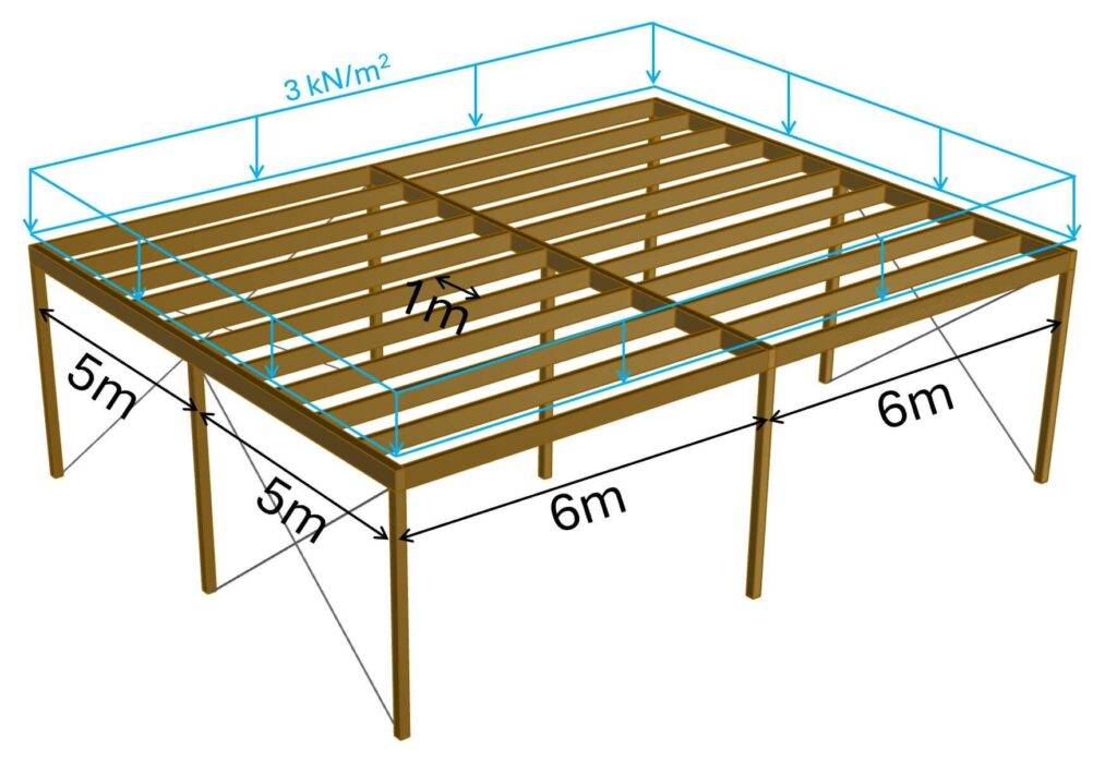
Step #2: Apply the vertical loads
We’ll use a design load of 3 kN/m2 as the area load on the roofing.
Step #3: Load transfer from top to bottom using the static systems
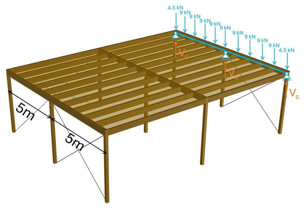
The spacing of the secondary beams is set to 1m (see picture above). Therefore, the line load on the secondary beams is calculated as:
$$p_{b.1} = 3 kN/m^2 \cdot 1m = 3 kN/m$$
Note that the 3 kN/m need to be applied to all secondary beams. And 3 kN/m /2 = 1.5 kN/m on the edge beams.
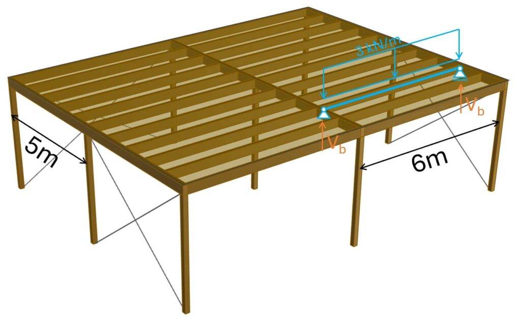
The reaction forces Vb are calculated as:
$$V_b = 3 kN/m \cdot 6m/2 = 9 kN$$
These 9 kN are now applied to the primary beams, which support the secondary beams.
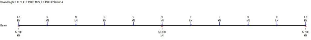
To calculate the reaction forces, I advise using a beam analysis software because continuous beams are statically indeterminate. This means that we can’t calculate reaction and internal forces using the 3 equilibrium equations.
At work, I use Polybeam. For this tutorial, I am using WinBeam because it’s for free.
We need to define E-modulus E and moment of inertia I of the beam, because they determine the stiffness of the beam and the stiffness has an influence on reaction forces of statically indeterminate beams.
E-modulus of structural timber C24:
$$E_{0.mean} = 11 kN/mm^2$$
Moment of inertia of a beam with width 20 cm and height 30 cm:
$$I = \frac{200mm \cdot (300mm)^3}{12} = 4.5 \cdot 10^8 mm^4$$
Applying the point loads to the beam result in reaction forces of 17.1 kN at start and end support and 55.8 kN at the center support.
These reaction forces can now be applied to the columns.
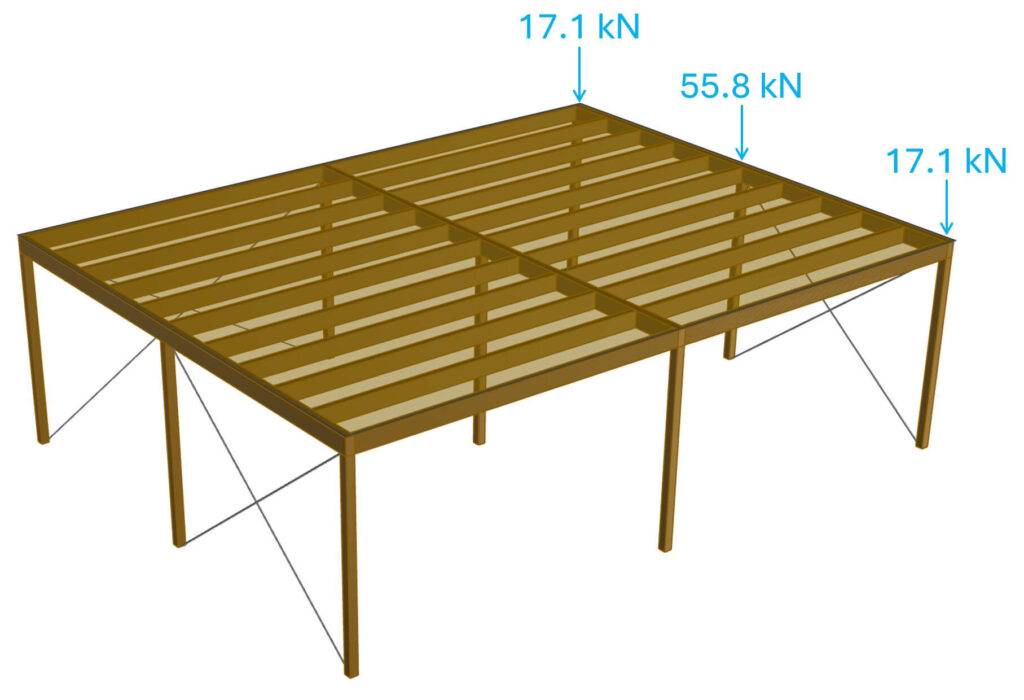
Now you can verify and design the timber columns for these loads.
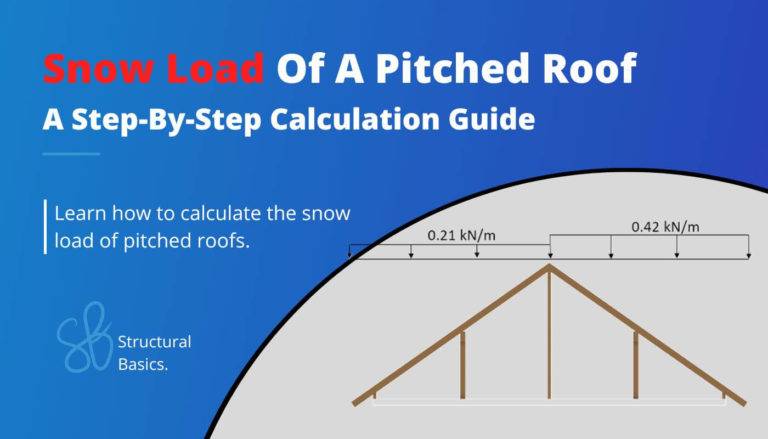
Example #3: Rafter Roof
Here’s a YouTube Short explaining how the vertical loads travel down to the foundation/soil from a rafter roof.
Example #4: In-Situ Concrete Slab Supported By Columns And Walls
In-situ concrete slabs are already a bit more tricky. I’ll get to the reasons in a second.
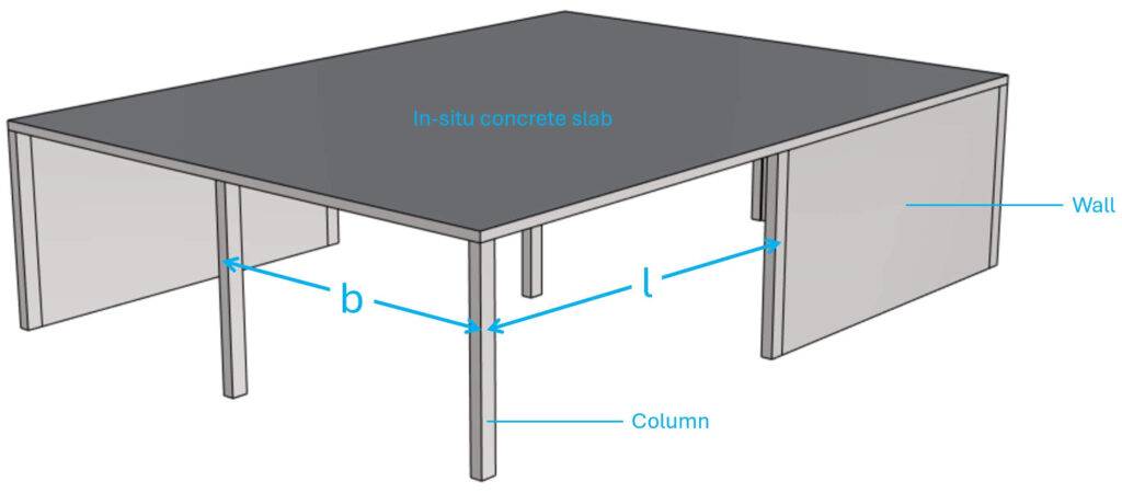
Step #1: Static systems of the structural elements
This is where it gets tricky. For an in-situ concrete slab with a regular layout/spacing of walls and columns, we can in theory use continuous beams to calculate the reaction forces and internal forces of the slab. I personally recommend only doing that to get a good estimate. You can check out my article about flat slab design, where I show how to calculate the internal forces of a slab with continuous beams.
I personally model in-situ concrete slabs in a FE program. This approach leads to the most accurate result. Also be aware that you rarely have a slab with such a regular spacing of columns and walls like in the example above.
Step #2: Apply the vertical loads
Step #3: Load transfer using the static systems
I’ll dive into how to design in-situ slabs with FE in a future article. It’s quite an advanced topic. There are many parameters that influence a FE model, and I’ve seen many bad models. But if you are interested in learning how to use continuous beams to calculate internal and reaction forces, then → check this article out ←.
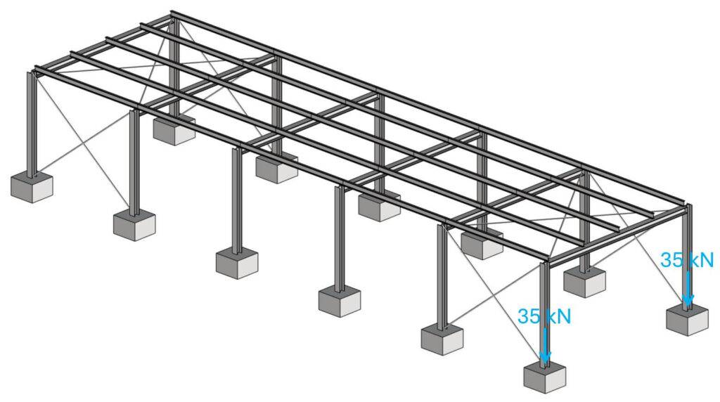
Example #5: Steel Or Timber Warehouse
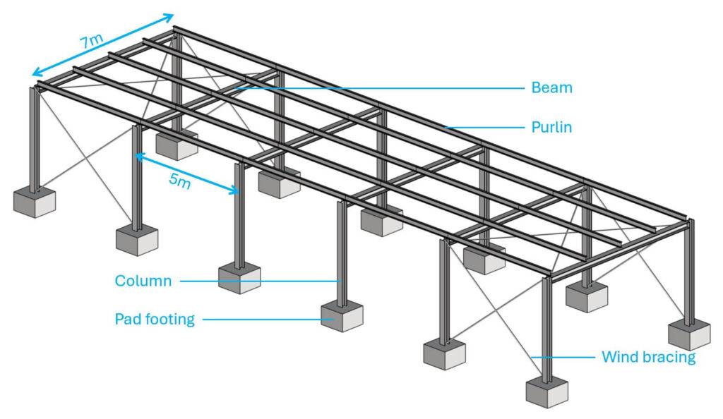
Step #1: Static systems of the structural elements
The static system depends on how you connect the beams to the columns and the columns to the foundation. But here are possible static systems of the structural elements.
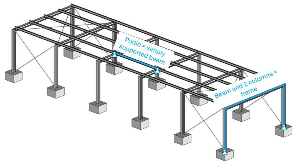
In the picture above, you can see that the beam and 2 columns work together as a frame.
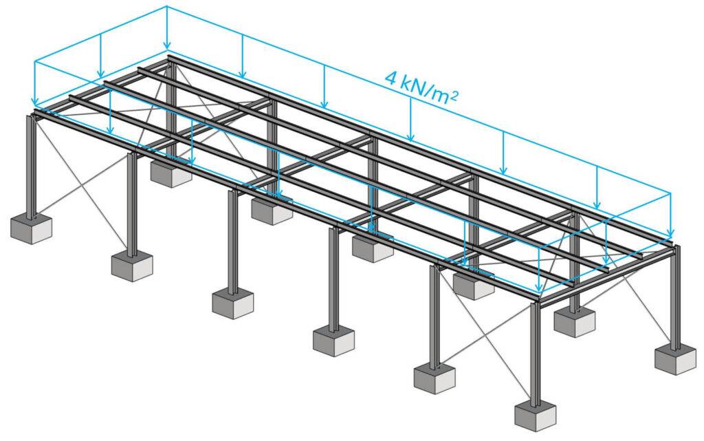
Step #2: Apply the vertical loads
Next, let’s apply a design load of 4 kN/m2 to the roof.
Step #3: Load transfer using the static systems
The spacing of the purlins is set to 1.75m (distance between them). Therefore, the line load on the purlin is calculated as:
$$q_p = 4 kN/m^2 \cdot 1.75m = 7 kN/m$$
We apply this line load on the purlins.
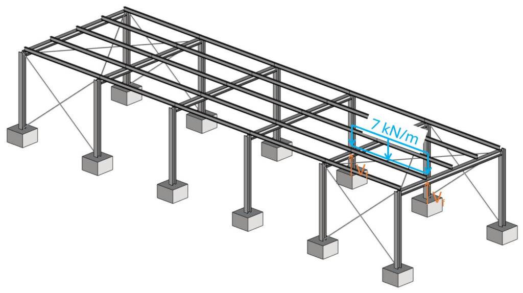
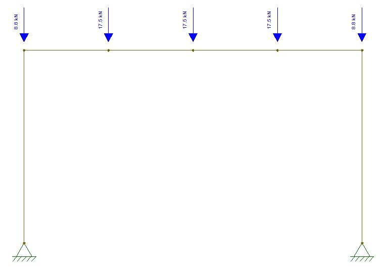
Next, we’ll calculate the reaction forces Vf and apply them to the frame.
$$V_f = 7 kN/m \cdot 5m/2 = 17.5 kN$$
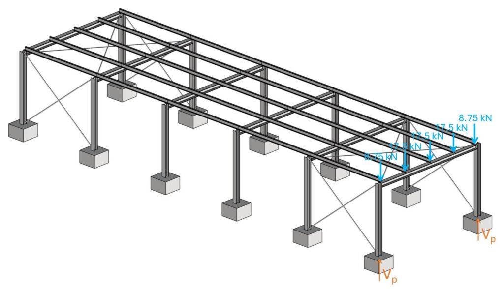
I usually calculate the internal forces and reaction forces of a frame structure like this in a FE program as a 3D model.
For this tutorial, I use Ftool, because it’s free, so you can also model the same frame.
And visualizing the normal forces shows us the vertical reaction forces.
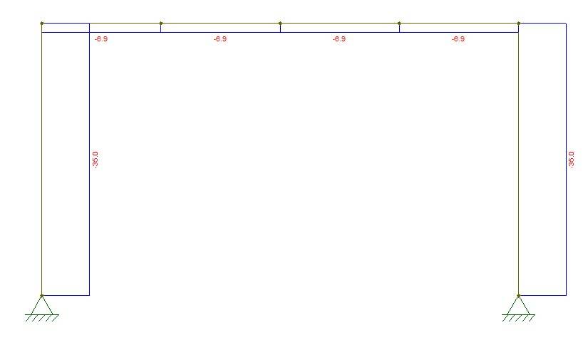
$$V_p = 35 kN$$
Now, for this simple frame with only vertical loading (which is also symmetric) we didn’t need a frame analysis software, because both supports take half of the vertical load. But as soon as something is unsymmetrical, or we add horizontal loading, we need a frame analysis software because most frames are statically indeterminate.
Finally, the reaction forces can be applied to the pad footings, and we can design the pad footings for these point loads.
Final Words
This was it! 5 example of how to do vertical load transfer. 💯💯
As already said, it’s a very complex topic and it takes a lot of practice and experience to master.
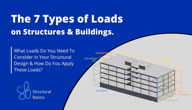
In this article, we’ll assumed the loads. But if you are interested in learning how to calculate vertical loads, then I recommend you check out our guide on the 7 different types of loads on buildings.

Laurin Ernst
![Wind Load Calculation On Walls [A Beginner’s Guide]](https://www.structuralbasics.com/wp-content/uploads/2022/02/Wind-loads-on-walls-768x439.jpg)
![Uniformly Distributed Load [All YOU Need To Know]](https://www.structuralbasics.com/wp-content/uploads/2023/04/Uniformly-distributed-loads-768x439.jpg)