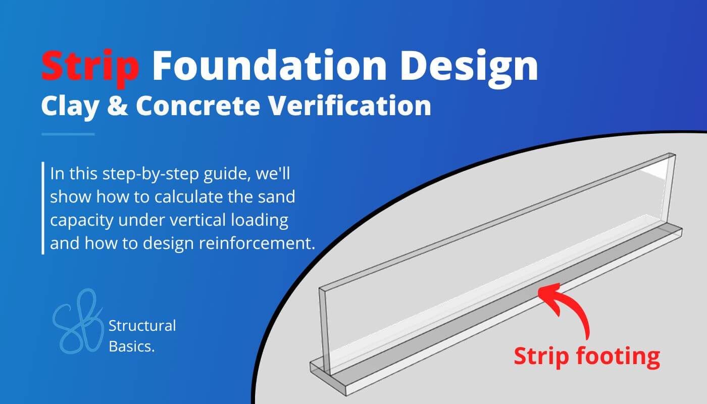
Strip Foundation In Clay {Design Of Soil And Concrete}
Designing a strip foundation is never really taught fully in university or textbooks. 🙈🙈
It’s either the geotechnical or the reinforced concrete design.
But both are necessary for structural documentation. 📄📄
That’s why in this post we’ll show you, step-by step, how to design a strip foundation in clay with a worked example. We’ll cover both the geotechnical verification of clay according to Eurocode EN 1997-1 and the reinforced concrete verification according to Eurocode EN 1992-1-1.
Not much more talk, let’s dive into it. 🚀🚀
🙋♀️ What Is A Strip Foundation?
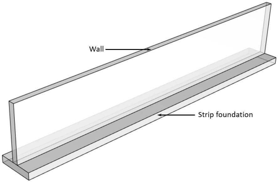
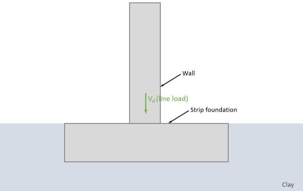
Strip foundations serve as a support system for walls in buildings. Typically, they consist of a concrete “block”, and in most cases steel reinforcement to resist tensile forces. These foundations are placed on soil and spread the concentrated load from the wall to a wider area of the soil.
Strip footings or foundations in general stand on sand, clay, rock, or a mix of 2 soil types. In this tutorial, we design a strip foundation which is embedded in clay.
Strip foundations usually have rectangular 🟦🟦 bases.
📃 Process of Strip Foundation Design
Before we dive into the nerdy calculations 😋😋, it’s good to get an overview of the steps that need to be taken to design a strip foundation, which is supported by clay and exposed to a vertical line load.
- Calculate characteristic loads that act on strip foundation
- Load combinations
- Define properties of the sand and concrete
- Geotechnical design – bearing resistance verification of clay
- Reinforced concrete design – bending verification
- Reinforced concrete design – shear verification
⬇️ Characteristic Loads
The loads of a structure depend on its location, geometry, building type and other factors.
We’ll assume in this tutorial that we design the strip foundation of a multi-storey building. 👇👇
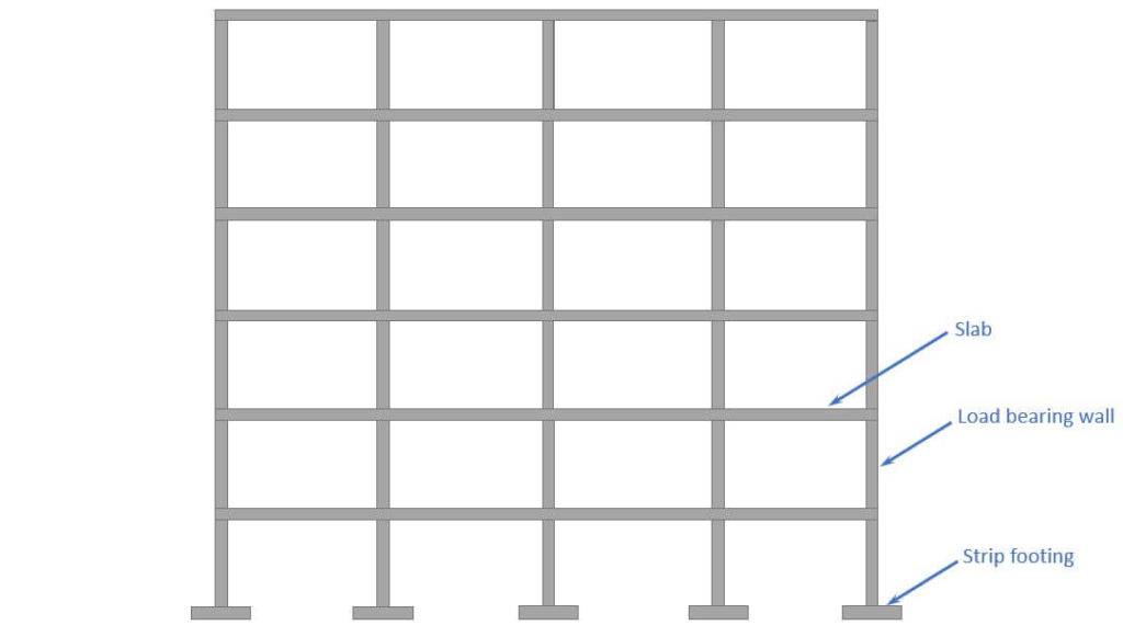
Now to calculate the characteristic loads acting on the strip foundation, we need to know what loads are applied where and how the loads travel through the different elements and to the foundations.
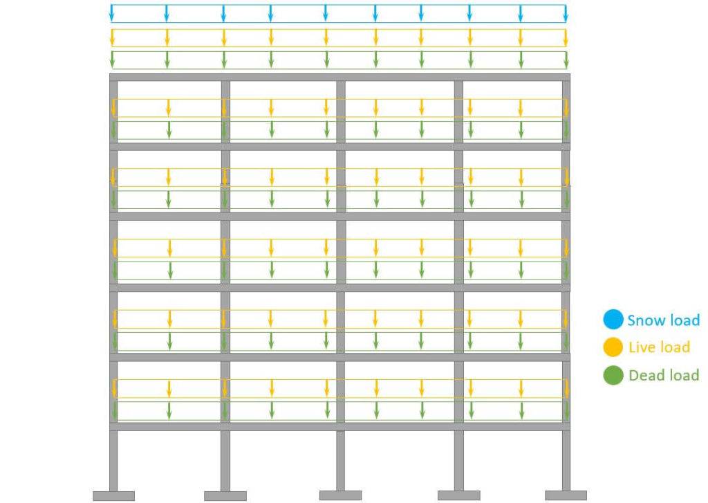
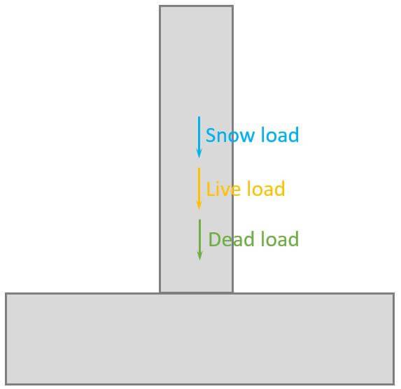
In this simplified design guide, the following vertical loads are considered:
Now, in the structural design of such a building, a lot more loads are considered such as seismic and wind load and imperfections.
But we’ll do a lot of assumptions in this tutorial. If you want to learn more about all the loads that act on a building, then check out this article.
Load transfer
❗ The following load transfer explanation works if the building is a traditional structure with simply supported beams and columns❗
- Live, snow and dead load (self-weight of roofing) are applied as area loads [kN/m2] on the roof. This could be precast hollow core slabs, which transfer the loads to beams and walls.
- The reaction force of a slab is then the characteristic vertical load that is applied to the wall.
- We do that for every floor, and the reaction forces are added up and applied to the strip foundation.
The following characteristic load values are assumptions.
| $g_{k}$ | 130 kN/m | Characteristic value of dead load |
| $q_{k}$ | 90 kN/m | Characteristic value of live load |
| $s_{k}$ | 5 kN/m | Characteristic value of snow load |
❗❗ The characteristic values of loads depend on a lot of different factors like location, National Annex and geometry of the building and roof to name just a few. Loads therefore need to be calculated for every structure. ❗❗
➕ Load combinations
Load combinations combine several load cases and multiply the characteristic loads with safety factors.
Check out our extensive article about load combinations to learn more about partial safety factors and how to set up the combinations.
ULS Load combinations
| LC1 | $1.35 \cdot 130 kN/m $ | $175.5 kN/m$ | |
| LC2 | $1.35 \cdot 130 kN/m + 1.5 \cdot 90 kN/m$ | $310.5 kN/m$ | |
| LC3 | $1.35 \cdot 130 kN/m + 1.5 \cdot 90 kN/m + 0.6 \cdot 1.5 \cdot 5 kN/m$ | $315 kN/m$ | |
| LC4 | $1.35 \cdot 130 kN/m + 1.5 \cdot 5 kN/m$ | $183 kN/m$ |
You can also use our load combination generator, which creates the load combinations automatically for you, and you can copy & paste the table into Word. 🔥🔥
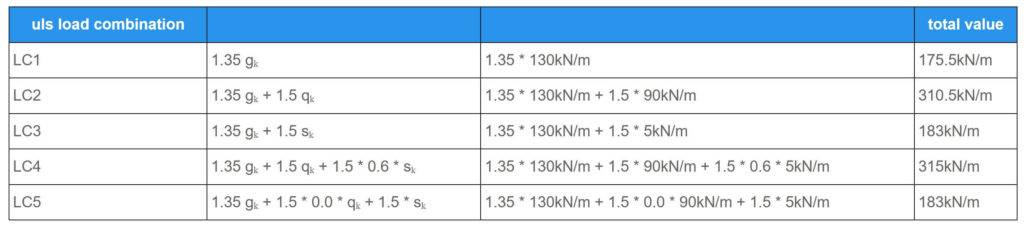
So the vertical design load we are designing the pad foundation for is:
$$V_{d} = 315 kN/m$$
🟫 Geotechnical Soil Properties
The strip foundation is embedded into the soil. In our example, it’s clay.
For this tutorial, we use the following soil properties.
| Density sand | $\gamma_{clay} = 18 kN/m^3$ | |
| Undrained shear strength | $c_u = 90 kN/m^2$ | |
| Partial factor (shear strength) Depends on the country | $\gamma_{cu} = 1.8$ | |
| Design undrained shear strength | $c_{ud} = \frac{c_u}{\gamma_{cu}} = 50 kN/m^2$ | |
| Density water | $\gamma_w = 10 kN/m^3$ | |
| Density wet sand | $\gamma ‘ = \gamma_{clay} – \gamma_w = 8 kN/m^3$ |
⬜ Concrete and Reinforcement Properties
For this tutorial, we use the following concrete and reinforcement properties.
| Concrete compression strength | $f_{c.k} = 25 MPa$ | |
| Concrete tensile strength | $f_{ctm} = 2.6 MPa$ | |
| Partial factor – in-situ Depends on the country | $\gamma_{c} = 1.45$ | |
| Design concrete compression strength | $f_{c.d} = \frac{f_{c.k}}{\gamma_{c}} = 17.24 MPa$ | |
| Design concrete tensile strength | $f_{c.t} = \frac{f_{ctm}}{\gamma_{c}} = 1.79 MPa$ | |
| Reinforcement yield strength | $f_{y.k} = 550 MPa$ | |
| Density concrete | $\gamma_c = 24 kN/m^3$ | |
| Concrete cover | $c = 50 mm$ | |
| Partial factor – reinforcement Depends on the country | $\gamma_{s} = 1.2$ | |
| $\epsilon_{cu3} = 0.35%$ | ||
| $\epsilon_{c3} = 0.175%$ | ||
| $\lambda = 0.8$ | ||
| $\epsilon_{yd} = 0.208%$ | ||
| $\eta = 1.0$ |
🕵️♂️ Geometry Of The Foundation And Wall
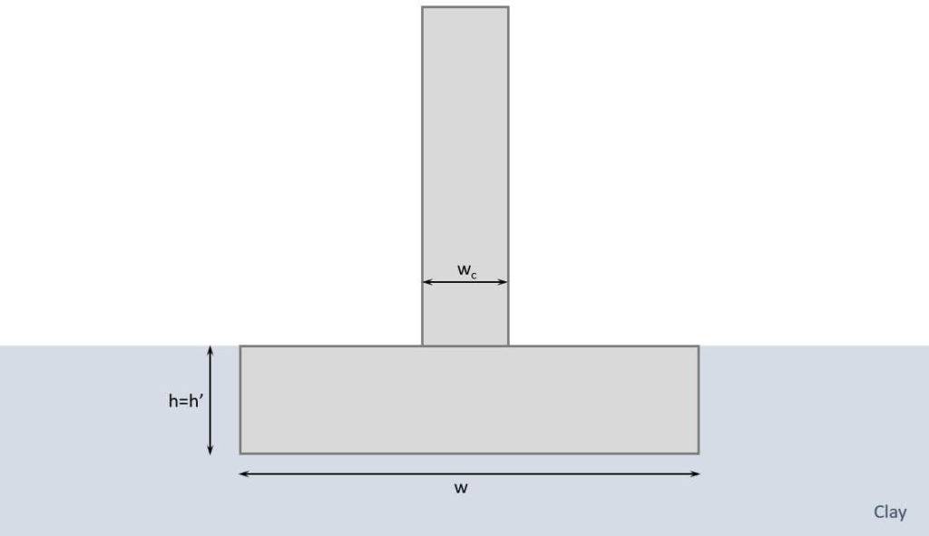
| Width | $w = 1.4 m$ | |
| Length | $l = \infty$ | |
| Height | $h = 0.5 m$ | |
| Depth of embedded foundation | $h’ = h = 0.5 m$ | |
| Width of column | $w_c = 0.3 m$ | |
| Inclination of the foundation base to the horizontal | $\alpha = 0$ | |
| Dead load of foundation (self-weight) | $g_k = w \cdot h \cdot \gamma_c = 16.8 kN/m$ | |
| New vertical design load | $V_d = V_d + 1.35 \cdot g_k = 322.7 kN/m$ |
Now, in countries, where the temperatures can get low, it’s common to have a minimum depth, where frost can’t affect the groundwater any more. Because if it does, it can lift up the foundation.
In Denmark, for example, 0.9 m is a common minimum depth.
✍️ Geotechnical Design – Bearing Resistance (EN 1997-1)
As we only have a vertical load acting on the pad foundation, we only have to verify that the design bearing resistance of the clay is greater than the design load. Let’s do that. 👍👍
For the final formula, we first need to calculate a lot of factors.
Shape factors (EN 1997-1 (D.1))
$$s_c = 1 + 0.2 \cdot \frac{w}{l} = 1.0$$
Inclination of loads (EN 1997-1 (D.1))
$$i_c = \frac{1}{2} \cdot (1 + \sqrt{1 – \frac{H_d}{w \cdot l \cdot c_{u.d}}}) = 1$$
Inclination of the foundation base (EN 1997-1 (D.1))
$$b_c = 1 – 2 \cdot \frac{\alpha}{\pi + 2} = 1$$
Effective vertical stresses
$$q = \gamma’ \cdot h’ = 4 kN/m^2$$
Design bearing resistance (EN 1997-1 (D.1))
$$\frac{R}{A} = (\pi + 2) \cdot c_{ud} \cdot b_c \cdot s_c \cdot i_c + q = 261.1 kN/m^2$$
$$R_d = 261.1 kN/m^2 \cdot w = 365.5 kN/m$$
Utilization
$$\eta = \frac{V_d}{R_d} = \frac{322.7 kN/m}{365.5 kN/m} = 0.88$$
Therefore, the bearing capacity of the soil (clay) is verified. 👍👍
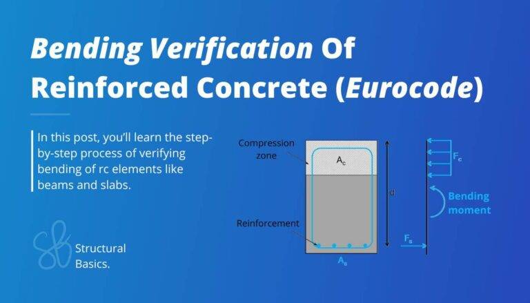
👨🔬 Reinforced Concrete Design – Bending Verification
First of all, strip footings don’t necessarily need reinforcement. In fact, most of the strip footings I have designed were unreinforced.
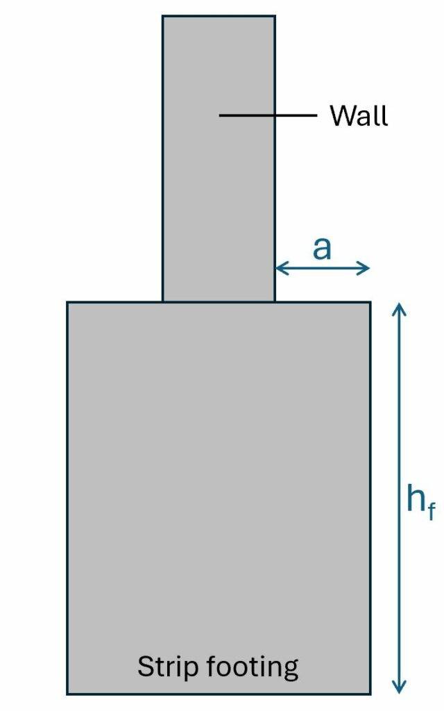
You can do that if the geometry of the footing follows EN 1992-1-1 12.9.3. The requirements are fulfilled if the cantilever part is less than half of the footing height.
$$a < \frac{h_f}{2}$$
Why is that?
It’s because all the load (soil pressure and concentrated line load from the wall) can be transferred in compression, because the angle of the load is > 60°.
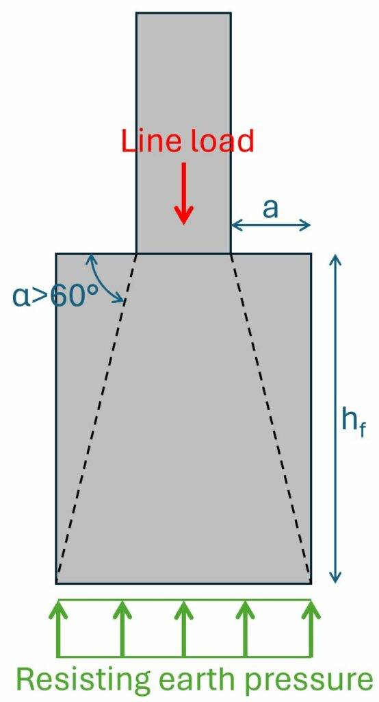
Now, if the soil doesn’t verify for this width, and we increase the width with the result that the angle < 60°, then we need to add reinforcement, which we’ll do in the following. 👇👇
A strut and tie model is used to transfer the line load to the soil and spread the load equally along the foundation base.
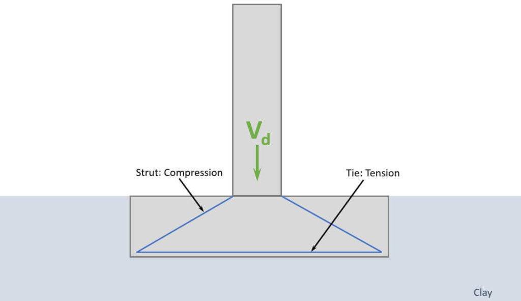
Now, as concrete can’t take much tension, reinforcement will be used for the tie, and we are going to calculate how much.
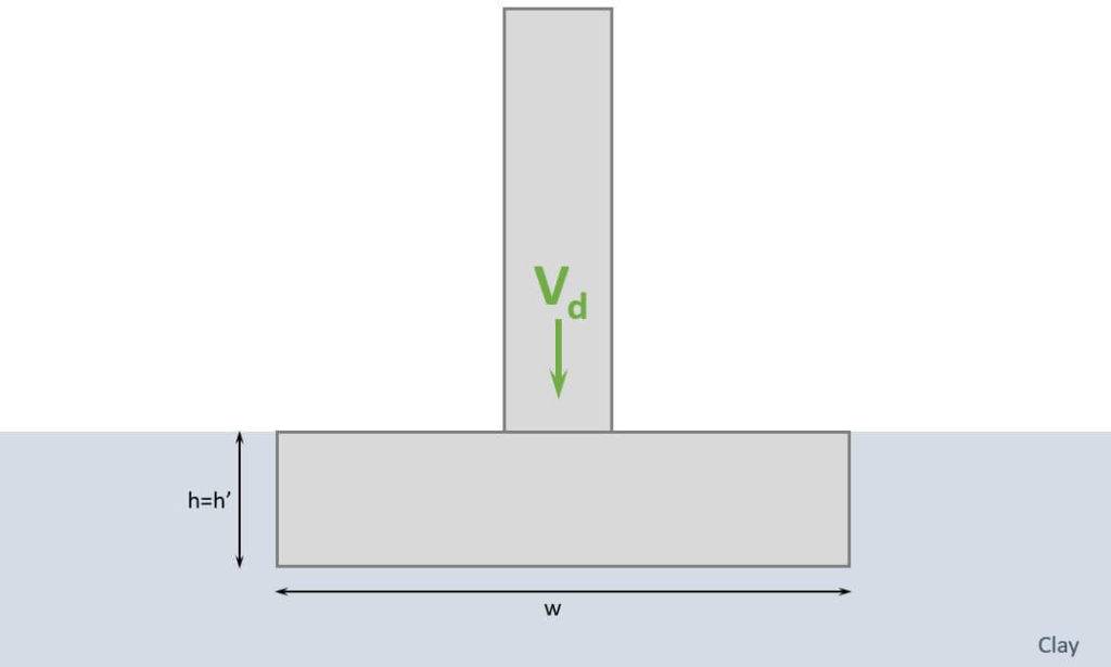
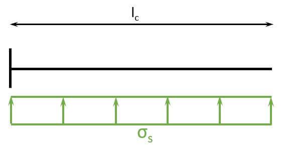
The compression zone of the strip foundation creates pressure in the soil, which is visualized in the next picture.
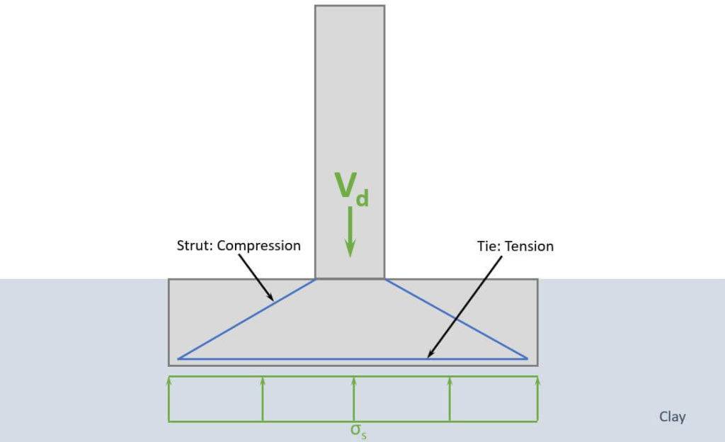
$$\sigma_s = \frac{V_d}{w \cdot 1m} = 230.5 kN/m^2$$
The soil pressure $\sigma_s$ creates a bending moment in the strip foundation, and we use a cantilever beam to calculate that bending moment.
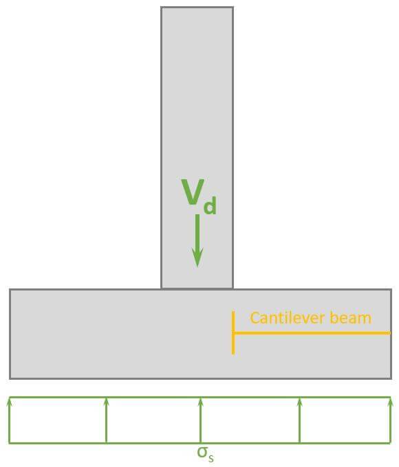
The length of the cantilever is $l_c = w/2 – w_c/2 = 0.55 m$
Now, the bending moment can be calculated.
$$M_{Ed} = \sigma_s \cdot 1m \cdot l_c \cdot l_c/2 = 230.5 kN/m^2 \cdot 1.4 m \cdot 0.55 m \cdot \frac{0.55 m}{2} = 34.9 kNm$$
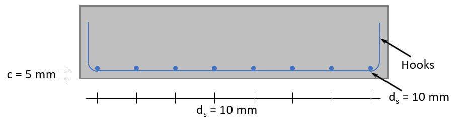
We set the diameter of the rebars to $d_s = 10 mm$.
The lever arm of the upper layer of reinforcement is calculated as
$$d = h – c – d_s – \frac{d_s}{2} = 0.43 m$$
The required reinforcement is calculated with the following formulas. 👇👇
$$\mu = \frac{M_{Ed}}{1m \cdot d^2 \cdot \eta \cdot f_{c.d}} = 0.011$$
$$\omega = 1 – \sqrt{1 – 2 \cdot \mu} = 0.011$$
$$A_{s.req} = \omega \cdot \frac{1m \cdot d \cdot \eta \cdot f_{c.d}}{f_{y.d}} = 175.8 mm^2$$
Check of minimum reinforcement according to EN 1992-1-1 9.2.1.1 (9.1N).
$$A_{s.min} = max(0.26 \cdot \frac{f_{ctm}}{f_{y.k}} \cdot 1m \cdot d; 0.0013 \cdot 1m \cdot d) = 565.5 mm^2$$
Because $A_{s.min} > A_s$, $A_{s.min}$ determines the reinforcement used.
Cross-sectional area of a rebar with $d_s = 10 mm$.
$$A_{s.1} = \pi \cdot (\frac{d_s}{2})^2 = 78.5 mm^2$$
Amount of rebars:
$$n = roundup(\frac{A_{s.min}}{A_{s.1}}) = 8$$
Reinforcement area:
$$A_s = n \cdot A_{s.1} = 628.3 mm^2 > A_{s.min}$$
Now, as the minimum reinforcement determined the reinforcement, we apply the same reinforcement to the longitudinal direction.
👩🏫 Reinforced Concrete Design – Shear Verification
In general, we want to avoid shear reinforcement in strip footings. We often rather change the geometry of the strip than add shear reinforcement.
To check if shear reinforcement is required, we’ll follow EN 1992-1-1 6.2.2.
In case, the design line load > design shear resistance without reinforcement, and you want to add shear reinforcement, we’ll follow EN 1992-1-1 6.2.3.
Members not requiring design shear reinforcement
EN 1992-1-1 6.2.2 (1)
$$k = 1 + \sqrt{\frac{200}{\frac{d}{mm}}} = 1.68$$
$$\rho_1 = min(\frac{A_s}{w \cdot d}; 0.02) = 0.001$$
Design value of the shear resistance (EN 1992-1-1 (6.2.a))
$$\upsilon_{Rd.c} = max(\frac{0.18}{\gamma_c} \cdot k \cdot (100 \rho_1 \cdot f_{c.k})^{\frac{1}{3}}; \frac{0.051}{\gamma_c} \cdot k^{\frac{3}{2}} \cdot \sqrt{f_{c.k}}) = 0.38 MPa$$
$$V_{Rd.c} = \upsilon_{Rd.c} \frac{\cdot w \cdot d}{1m} = 232.8 kN/m$$
Shear reinforcement required because $V_d > V_{Rd.c}$.
Members requiring design shear reinforcement
EN 1992-1-1 Figure 6.5
$$z = 0.9 \cdot d = 0.39m$$
Coefficient taking into account the state of the stress in the compression chord:
$$\alpha_{cw} = 1.0$$
Strength reduction factor for concrete cracked in shear (EN 1992-1-1 (6.9))
$$\upsilon_1 = 0.6$$
$$cot(\theta) = 2.5$$
$$tan(\theta) = 0.4$$
Shear resistance (EN 1992-1-1 (6.9))
$$V_{Rd.max} = \alpha_{cw} \cdot w \cdot z \cdot \upsilon_1 \cdot \frac{f_{c.d}}{cot(\theta) + tan(\theta)} = 1955 kN$$
Verification is fulfilled. 👇👇
$$V_d < V_{Rd.max} = 1$$
Reduction of the design yield strength of the reinforcement (EN 1992-1-1 (6.8))
$$f_{ywd} = 0.8 \cdot f_{y.k} = 440 MPa$$
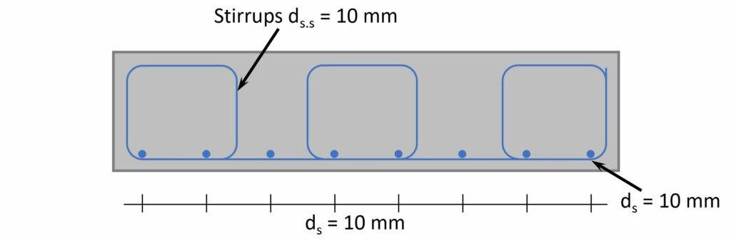
Shear links (EN 1992-1-1 (6.8))
$$A_{sw} = \frac{V_d \cdot 1m}{z \cdot f_{ywd} \cdot cot(\theta)} = 749.3 \frac{mm^2}{m}$$
Inclination of the shear reinforcement
$$\alpha = 90 deg$$
Maximum spacing (EN 1992-1-1 (9.6N))
$$s_{l.max} = 0.75 \cdot d \cdot (1 + cot(\alpha)) = 0.326 m $$
We set the spacing of the bars to s = 250 mm.
Shear reinforcement required for the whole width:
$$A_{sw} = A_{sw} \cdot w = 1049 mm^2$$
Amount of bars:
$$n = roundup(\frac{w}{s}) = 6$$
Required cross-sectional area for one stirrup:
$$A_{sw.req} = \frac{A_{sw}}{2 \cdot n} = 87.4 mm^2$$
Required bar diameter:
$$d_{s.req} = \frac{2 \cdot \sqrt{A_{sw.req}}}{\pi} = 6 mm$$
Therefore, a stirrup diameter of $d_{s.s} = 10 mm$ is picked.
🙌 Conclusion
Once the bearing capacity of the clay, longitudinal and shear reinforcement of the strip foundation are verified, we successfully designed the strip foundation. 💯💯
If you are new to structural design, then check out more of our design tutorials where you can also learn how to design wood elements such as
But now, I would like to hear from you: Have you already designed a strip foundation in university or at your work? And which semester was that in? Tell us a bit about the structure it was supporting, as we all want to learn from each other. ✍️✍️

🙋♂️ Strip Foundation On Clay FAQ
For only vertical loading, you have to verify the following 3 things:
– Bearing resistance of clay > Vertical design load
– Design the bending reinforcement
– Design the shear reinforcement
For the geotechnical design Eurocode 7 (EN 1997-1) is used if you are in Europe. For the concrete and reinforcement design Eurocode 2 (EN 1992-1-1) applies.
![Timber Beam Design [Step-By-Step]](https://www.structuralbasics.com/wp-content/uploads/2022/01/Wood-timber-beam-design-Bending-moment-shear-and-deformation-verification-kmod-strength-768x439.png)