Shear Verification Without Shear Reinforcement [Eurocode]
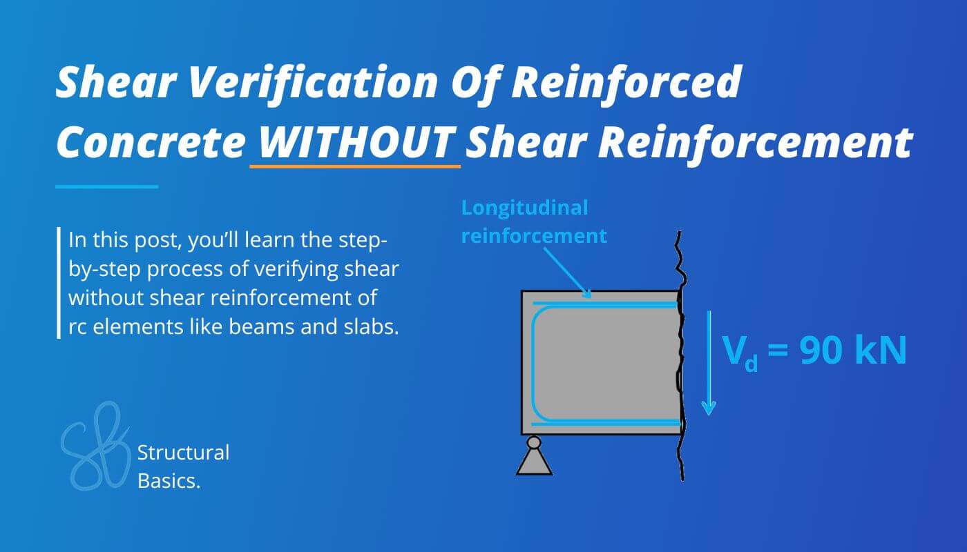
The title “shear verification without shear reinforcement” is a bit weird, isn’t it? How do you verify shear without having shear reinforcement?
Let me explain.
In general for beams in my job as a structural engineer I would always use shear reinforcement like stirrups, but there are other elements where it’s either hard to fit stirrups in – like 200mm thick slabs. Or there it just also verifies without shear reinforcement (strip footings in some cases).
In this article, we’ll check out how we can make reinforced concrete work without having shear reinforcement, according to Eurocode.
Let’s get into it.
Step-By-Step Process To Verify Shear Of Reinforced Concrete Without Shear Reinforcement
Here’s the step-by-step process I always follow when verifying shear without shear reinforcement for reinforced concrete elements like slabs, strip footings, walls, etc.:
Step #1: Defining the properties of concrete and reinforcement
Step #2: Lever arm and cross-sectional area of the longitudinal reinforcement
Step #3: Calculation of the design value of the shear resistance according to EN 1992-1-1 6.2.2
Step #4: Verifying that the shear force VEd < the shear resistance without shear reinforcement VRd.c
In the next section, we’ll look at an example and run through all #4 steps in detail.
Shear Verification Of Reinforced Concrete Without Shear Reinforcement In 4 Steps
To run through the #4 steps to verify shear without shear reinforcement, we’ll use a beam cross-section with width w = 300mm and height h = 550 mm. You can apply this workflow also for slabs. Instead of the width of the beam in the formulas, use 1m.
Shear without reinforcement is verified with EN 1992-1-1 6.2.2.
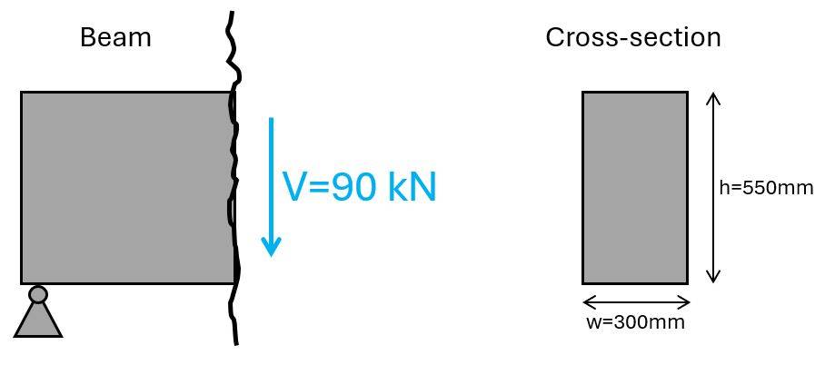
What many don’t know, you can also decrease the shear force, depending on the width of your support. I explained it in detail in this YouTube video.
Step #1: Define the properties of concrete and reinforcement
The reinforced concrete beam we’ll use in this tutorial has the following concrete (C25) and reinforcement properties.
| Concrete compression strength | fc.k = 25 MPa |
| Concrete tensile strength | fctm = 2.6 MPa |
| Partial factor in-situ concrete (Denmark) | γc = 1.45 |
| Design concrete compression strength | fc.d = fc.k/γc = 17.2 MPa |
| Design concrete tensile strength | ft.d = fctm/γc = 1.8 MPa |
| Concrete cover | c = 30 mm |
| Reinforcement yield strength | fy.k = 550 MPa |
| Partial factor reinforcement concrete (Denmark) | γs = 1.2 |
| Design yield strength | fy.d = fy.k/γs = 458.3 MPa |
Step #2: Lever arm and cross-sectional area of the longitudinal reinforcement
The lever arm or effective height of the longitudinal rebars is the distance from the centre of the reinforcement to the top or bottom fibre of the cross-section which is in compression.
In our case (with a positive bending moment) it’s the distance from the bottom longitudinal reinforcement to the top fibre of the section.
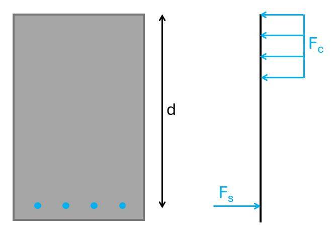
For a diameter of the longitudinal reinforcement of ds = 25 mm, the lever arm is calculated as:
$$d = h – c – d_s/2 = 498 mm$$
From the picture above, we see that we’ll use 4 longitudinal rebars, which have an area of:
$$A_s = 4 \cdot \pi \cdot (\frac{25mm}{2})^2 = 1963 mm^2$$
Step #3: Calculate the design value of the shear resistance according to EN 1992-1-1 6.2.2
The design value of the shear resistance for members not requiring shear reinforcement is calculated according to EN 1992-1-1 (6.2.a):
$$\upsilon_{Rd.c} = max(\frac{0.18}{\gamma_c} \cdot k \cdot (100 \rho_1 \cdot f_{c.k})^{1/3}; \frac{0.051}{\gamma_c} \cdot k^{3/2} \cdot \sqrt{f_{c.k}}) = 0.64 MPa$$
With,
$$k = 1 + \sqrt{\frac{200}{d}} = 1.63$$
$$\rho_1 = min(\frac{A_s}{w \cdot d}; 0.02) = 0.013$$
Step #4: Verify that the shear force VEd < the shear resistance without shear reinforcement VRd.c
Before the verification, let’s transform the shear resistance νRd.c from a stress [MPa] into a force [kN].
$$V_{Rd.c} = \upsilon_{Rd.c} \cdot w \cdot d = 97 kN$$
This leads to a utilization of:
$$\eta = \frac{90 kN}{V_{Rd.c}} = 93 \% \rightarrow OK!$$
And the beam is verified for shear without shear reinforcement.
Final words
To be honest with you, I have always used shear reinforcement in beams.
But I have always designed reinforced concrete slabs without shear reinforcement. And for these slabs, I verify shear with exactly the formulas we just went through.
One thing that I want you to learn and remember is that the longitudinal reinforcement, and it’s lever arm, have a big influence on the shear capacity (until a certain point – As → ρ1 = 0.02). It’s not only stirrups. Look at the formulas above again.
The bigger d, the bigger VRd.c and the bigger As, the bigger VRd.c. But for As there is a limit. Once ρ1 = 0.02, a bigger cross-sectional area of the reinforcement doesn’t help any more.
If you don’t want to miss any new structural design tutorials, then subscribe to our free weekly newsletter.
Or subscribe to my YouTube channel for regular updates.

Laurin Ernst
![Masonry Wall Subjected To Point Load [Step-By-Step Guide]](https://www.structuralbasics.com/wp-content/uploads/2024/03/Masonry-wall-subjected-to-point-load-768x439.jpg)
