Shear Verification WITH Shear Reinforcement {Reinforced Concrete}
Every reinforced concrete beam needs to be checked and designed for shear because if the shear force is bigger than the shear resistance without shear reinforcement, shear cracks develop and the beam might fail.
In this article, I show you how to verify and design shear reinforcement of reinforced concrete elements like beams and slabs in 5 steps..
If you prefer video, then check out my YouTube tutorial on how to verify shear in rc beams.
Now, let’s get into it.
Step-By-Step Process To Verify Shear Of Reinforced Concrete With Shear Reinforcement
Here’s the step-by-step process I always follow when verifying shear with shear reinforcement for reinforced concrete elements like beams, slabs, strip footings, walls, etc.:
Step #1: Defining the properties of concrete and reinforcement
Step #2: Lever arm and cross-sectional area of the longitudinal reinforcement
Step #3: Calculation of the design value of the shear resistance according to EN 1992-1-1 6.2.2
Step #4: Verifying that the shear force VEd < the shear resistance without shear reinforcement VRd.c
Step #5: Calculate and define the spacing of the shear reinforcement
In the next section, we’ll look at an example and run through all #5 steps in detail.
Shear verification with shear reinforcement in 5 steps
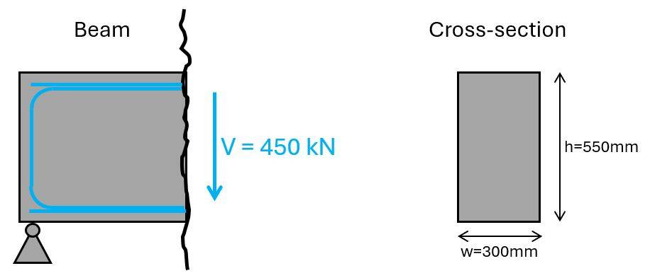
We’ll use the same beam cross-section as in our bending and shear verification without shear reinforcement tutorials. The shear force we’ll use is 450 kN.
Shear with reinforcement is verified with EN 1992-1-1 6.2.2.
There are different approaches to the steps, we do in the following. We are going to verify the diameter of the stirrups. But you can also choose to verify shear capacity. This is up to you.
Step #1: Define the properties of concrete and reinforcement
Here are the concrete and reinforcement properties, we use in this tutorial.
| Concrete compression strength | fc.k = 25 MPa |
| Concrete tensile strength | fctm = 2.6 MPa |
| Partial factor in-situ concrete (Denmark) | γc = 1.45 |
| Design concrete compression strength | fc.d = fc.k/γc = 17.2 MPa |
| Design concrete tensile strength | ft.d = fctm/γc = 1.8 MPa |
| Concrete cover | c = 30 mm |
| Reinforcement yield strength | fy.k = 550 MPa |
| Partial factor reinforcement concrete (Denmark) | γs = 1.2 |
| Design yield strength | fy.d = fy.k/γs = 458.3 MPa |
Step #2: Lever arm and cross-sectional area of the shear & longitudinal reinforcement
The lever arm or effective height of the longitudinal reinforcement is the distance of the center of the reinforcement to the top or bottom fibre of the cross-section which is in compression.
In our case (with a positive bending moment – simply supported beam) it’s the distance from the bottom longitudinal reinforcement to the top fibre of the section.
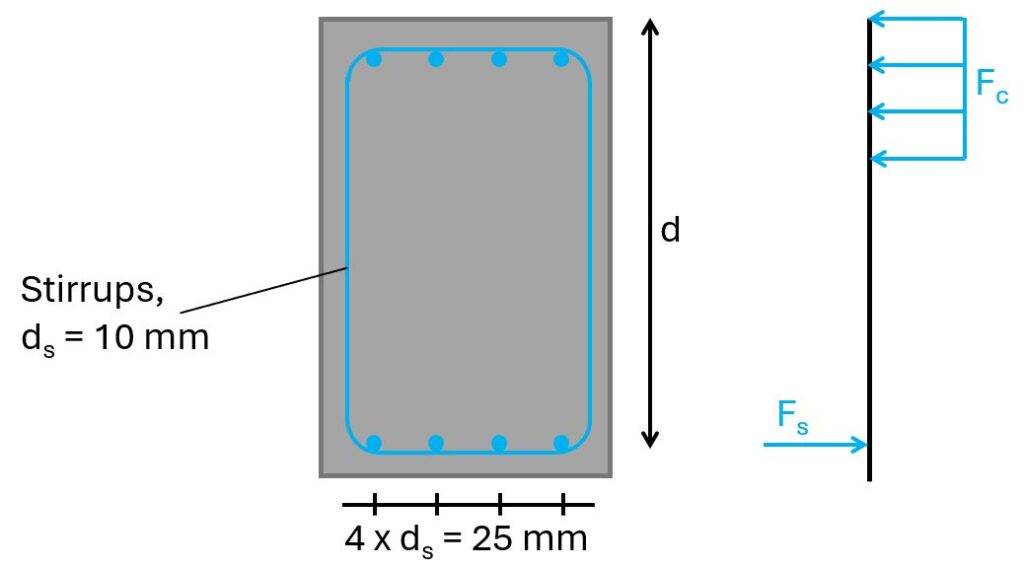
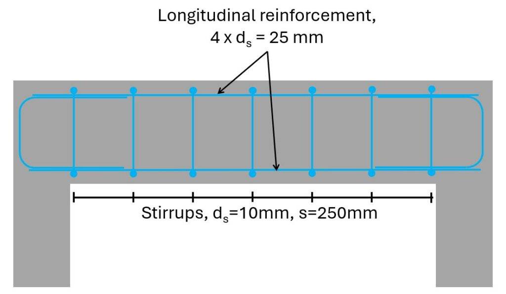
For a diameter of the longitudinal reinforcement of ds = 25 mm and the stirrups of dv = 10 mm, then the lever arm is calculated as:
$$d = h – c – d_s/2 = 498 mm$$
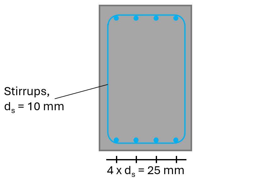
From the picture above, we see that we’ll use 4 longitudinal rebars, which have an area of:
$$A_s = 4 \cdot \pi \cdot (\frac{25mm}{2})^2 = 1963 mm^2$$
The cross-sectional area of 1 stirrup with a diameter of 10mm with 2 vertical rebars is calculated as:
$$A_{sw} = 2 \cdot \pi \cdot (\frac{10mm}{2})^2 = 157 mm^2$$
Step #3: Calculate the design value of the shear resistance with shear reinforcement according to EN 1992-1-1 6.2.2
The design value of the shear resistance for members requiring shear reinforcement is calculated according to EN 1992-1-1 (6.9):
$$V_{Rd.max} = \alpha_{cw} \cdot w \cdot z \cdot \upsilon_1 \cdot \frac{f_{c.d}}{cot(\theta) + tan(\theta)} = 479.1 kN$$
With,
- ν1 = 0.6 according to EN 1992-1-1 (6.9) as a strength reduction factor for concrete cracked in shear
- αcw = 1.0 as a coefficient taking into account the state of stress in the compression chord
- z = 0.9 ⋅ d = 448 mm (EN 1992-1-1 Figure 6.5)
- cot(θ) = 2.5 → EN 1992-1-1 (6.7N)
- tan(θ) = 0.4 → EN 1992-1-1 (6.7N)
Step #4: Verify that the shear force VEd < the design shear resistance with shear reinforcement VRd.max
A design shear force of 450 kN and a shear resistance of 479 kN lead to a utilization of:
$$\eta = \frac{450 kN}{479 kN} = 94 \% < 100 \% \rightarrow OK!$$
Step #5: Calculate and define the spacing of the shear reinforcement
As a last step, we’ll calculate the spacing of the stirrups.
First, according to EN 1992-1-1 (6.8), we’ll reduce the design yield strength of the reinforcement:
$$f_{ywd} = 0.8 \cdot f_{y.k} = 440 MPa$$
The required cross-sectional area of the shear links is calculated with EN 1992-1-1 (6.8):
$$A_{sw} = \frac{V_d}{z \cdot f_{ywd} \cdot cot(\theta)} = 913.7 \frac{mm^2}{m}$$
The shear reinforcement (=stirrups) is vertical. Therefore, α is set to:
$$\alpha = 90°$$
The maximum spacing is calculated with EN 1992-1-1 (9.6N)):
$$s_{l.max} = 0.75 \cdot d \cdot (1 + cot(\alpha)) = 373 mm$$
We therefore set the spacing of the spacing of the stirrups to:
$$s = 250 mm$$
→ Required cross-sectional area of the shear reinforcement of 1 stirrup:
$$A_{sw} = A_{sw} \cdot s = 228 mm^2$$
The required cross-sectional area of 1 stirrup is therefore (1 stirrup has 2 vertical “rebars”):
$$A_{sw.req} = \frac{A_{sw}}{2} = 114 mm^2$$
And the required bar diameter:
$$d_{s.req} = \frac{2 \cdot \sqrt{A_{sw.req}}}{\pi} = 6.8 mm$$
Now, we could reduce the stirrup diameter from 10mm to 8mm, or just leave it to have some extra capacity. In general, I always like to have some extra capacity. It often times saves you (and your design) when design changes come from the architect or if someone forget to tell you that the live load was changed from 1.5 kN/m2 to 3.0 kN/m2.
Final words
This was one of these endless weekends of studying and researching about shear in rc elements. In the end, it took me 10 hours to write this article. But it was fun and I can say that I understand shear on a deeper level now.
If you don’t want to miss any new structural design tutorials, then subscribe to our free weekly newsletter.
Or subscribe to my YouTube channel for regular updates.
Let’s design better structures together,
Laurin.

Laurin Ernst
![Compression Verification Of Reinforced Concrete [Eurocode]](https://www.structuralbasics.com/wp-content/uploads/2024/10/Compression-verification-of-reinforced-concrete-768x439.jpg)
![Rafter Roof Design [Step-By-Step Guide]](https://www.structuralbasics.com/wp-content/uploads/2022/04/Rafter-Roof-Design-1-768x439.jpg)
![Timber Truss Roof Design [A Structural Guide]](https://www.structuralbasics.com/wp-content/uploads/2022/04/Timber-Truss-Roof-Design-768x439.jpg)