Punching Shear Design {Step-By-Step Guide}
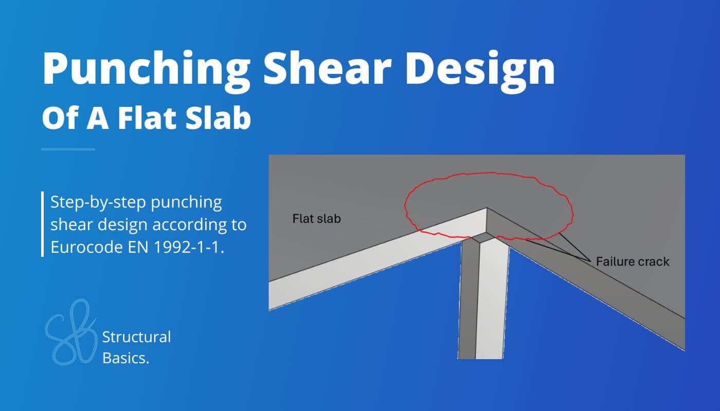
Punching shear is a phenomenon in structural engineering which describes the failure of flat slabs due to concentrated loads such as columns.
In this guide, we’ll show step-by-step, how you design and verify flat slabs for punching shear.
Let’s get started. 🚀🚀
What Is Punching Shear And Where Does It Happen?
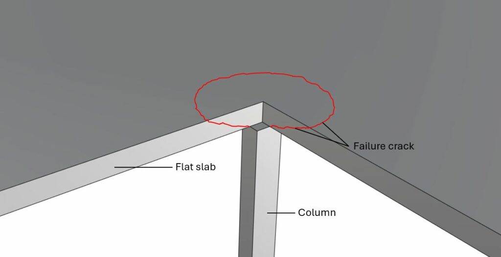
Punching shear is a type of shear failure that occurs close to where a concentrated load is applied to a slab. The failure happens in a cicular shape around the concentrated load. The 2 main situations where punching shear occurs are:
- flat slabs supported by a column and
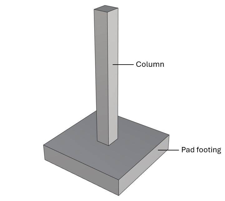
- pad footings or foundation rafts that support a column.
The design and verification of punching shear is covered by EN 1992-1-1 6.4.
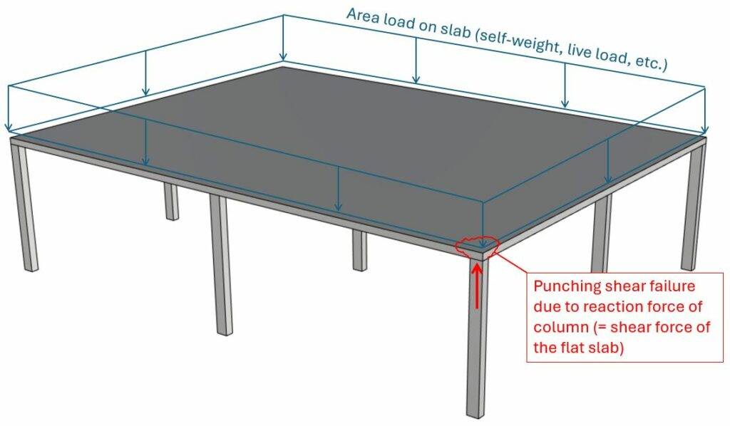
Punching shear in flat slabs supported by columns
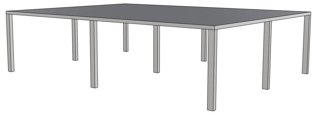
Punching shear has to be verified for flat slabs that are supported by columns as in the next picture. The most critical will be at the center column as this column takes up the most load.
Punching shear in pad footings supporting columns
Process of Punching Shear Design
Before we dive into the nerdy calculations, it’s good to get an overview of the steps that need to be taken to design and verify punching shear. 👇👇
- Define geometry properties of the slab and column
- Calculate characteristic area loads that act on the slab
- Load combinations to find the design loads
- Define material properties of the slab and column
- ULS punching shear verification without shear reinforcement
- ULS punching shear verification with shear reinforcement
We are showing all calculation steps for the following simplified example where 9 columns support a reinforced concrete slab.
In this post, we’ll verify punching shear for the slab above the center column, because it’s the most critical location of the slab leading to the highest shear force.
1. Geometry Properties Of The Slab And Column
The slab and the column have the following geometric properties:
| Slab/Plate thickness | $t_{p} = 0.2 m$ |
| Column cross-section width | $w = 0.2 m$ |
| Column cross-section height | $h = 0.3 m$ |
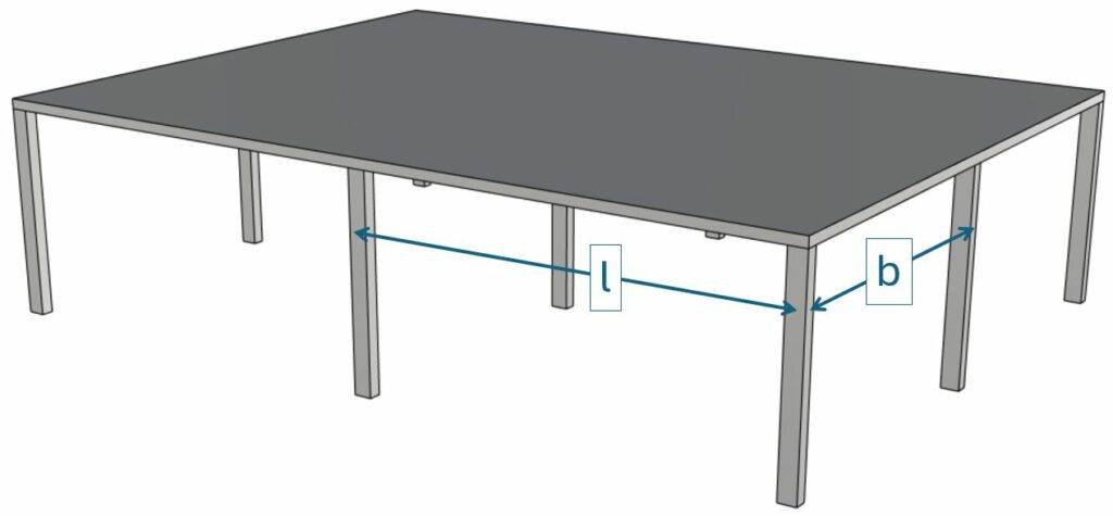
| Column spacing | $l = 7.5 m$ |
| Column spacing | $b = 6.5 m$ |
2. Characteristic Loads
In this tutorial we’ll simplify the calculation of the loads. We assume that we design a reinforced concrete slab with thickness tp = 0.2m that is supported by 9 columns. The slab is exposed to the following area loads: ⬇️⬇️
| Characteristic dead load of the rc slab | $g_{k.s} = 25 kN/m^3 \cdot t_p = 5 kN/m^2$ |
| Characteristic dead load of the flooring | $g_{k.f} = 1.6 kN/m^2$ |
| Live load (value for offices in Denmark) | $q_k = 2.5 kN/m^2$ |
Load transfer
The vertical area loads are taken up by the reinforced concrete slab and transferred to the columns. In regular cases like our example where the column distance is the same, we can use formulas to calculate the reaction forces of the columns (shear force of the slab).
However, the more irregular the supports of the slab are, the better and more accurate it is to use a FE model.
We use the formula of a 2-span continuous beam to find the reaction force of the center column.
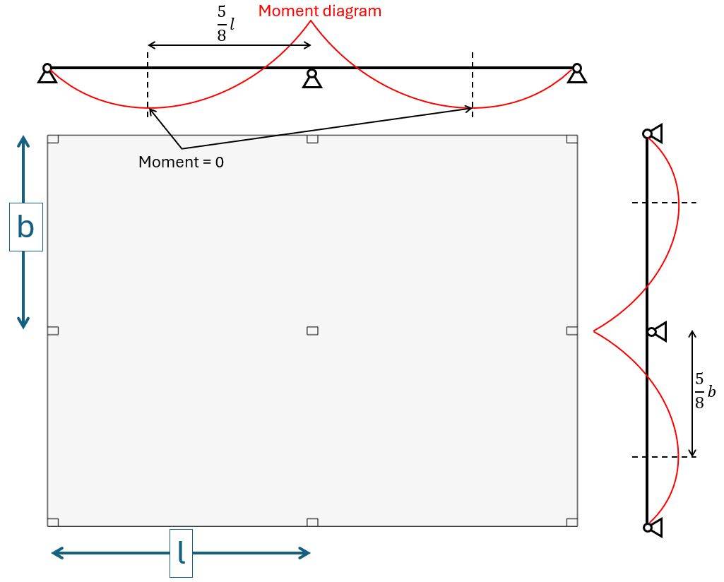
$$V_{Ed} = 2 \cdot \frac{5}{8} \cdot l \cdot 2 \cdot \frac{5}{8} \cdot b \cdot q_d$$
As a next step, let’s find the design area load qd. 👇👇
3. Load Combinations
Load combinations combine several load cases and multiply the characteristic loads with safety factors.
Luckily, we have already written an extensive article about what load combinations are and how we use them.
In case you need to brush up on it or want to check how we derived the safety factors, you can read the blog post here.
ULS load combinations
| LC1 | $1.35 \cdot (g_{k.s} + g_{k.f}) + 1.5 \cdot q_k $ | $12.67 kN/m^2$ |
Now, in our case, we only use one load combination, because we simplify this tutorial. Usually, you have to consider multiple load combinations. However, from experience, we can say that for an indoor office slab, this load combination is governing in most situations.
With the design load qd of 12.67 kN/m2, we can now calculate the shear force of the slab at the location of the center column: 👇👇
$$V_{Ed} = 2 \cdot \frac{5}{8} \cdot l \cdot 2 \cdot \frac{5}{8} \cdot b \cdot q_d = 964.3 kN$$
💡💡 Info:
If you calculate the shear force of the slab / normal force of the column with a FE model, you won’t get the exact same result. The beams and slabs don’t have exactly the same behaviour, and we used beam formulas to calculate the reaction forces. The stiffness of the slab and columns in the FE model also have an influence of the size of the reaction forces.
4. Concrete and Reinforcement Properties
| Concrete compression | $f_{c.k} = 30 MPa$ |
| Partial factor in-situ concrete (Denmark) | $\gamma_c = 1.45$ |
| Design concrete compression strength | $f_{c.d} = 20.7 MPa$ |
| Reinforcement yield strength | $f_{y.k} = 500 MPa$ |
| Partial factor reinforcement (Denmark) | $\gamma_s = 1.2$ |
| Design yield strength | $f_{y.d} = \frac{f_{y.k}}{\gamma_s} = 416.7 MPa$ |
| Rebar cover | $c = 30 mm$ |
We’ll also assume the longitudinal reinforcement of the slab. Keep in mind that we didn’t calculate that.
| Rebar diameter (x-direction) | $d_{s.x} = 10 mm$ |
| Spacing of rebars (x-direction) | $a_x = 100 mm$ |
| Reinforcement area (x-direction) | $A_{s.x} = \pi \cdot (\frac{d_{s.x}}{2})^2 = 78.54 mm^2$ |
| Rebar diameter (y-direction) | $d_{s.y} = 10 mm$ |
| Spacing of rebars (y-direction) | $a_y = 100 mm$ |
| Reinforcement area (y-direction) | $A_{s.x} = \pi \cdot (\frac{d_{s.x}}{2})^2 = 78.54 mm^2$ |
5. ULS Punching Shear Verification Without Shear Reinforcement
The following checks have to be carried out according to EN 1992-1-1 6.4.3 (2):
- At the perimeter of the loaded area (column perimeter) the maximum shear resistance stress should not be exceeded:
$$\tau_{Ed} < \tau_{Rd.max}$$ - Punching reinforcement is not required if the shear stress does not exceed the punching shear resistance without punching reinforcement along the control section:
$$\tau_{Ed} < \tau_{Rd.c}$$ - If $\tau_{Ed} > \tau_{Rd.c}$ punching reinforcement must be added and verified.
We start by calculating the effective depth of the longitudinal reinforcement by finding the depths of the reinforcement in x- and y- direction.
$$d_{eff} = \frac{d_x + d_y}{2}$$
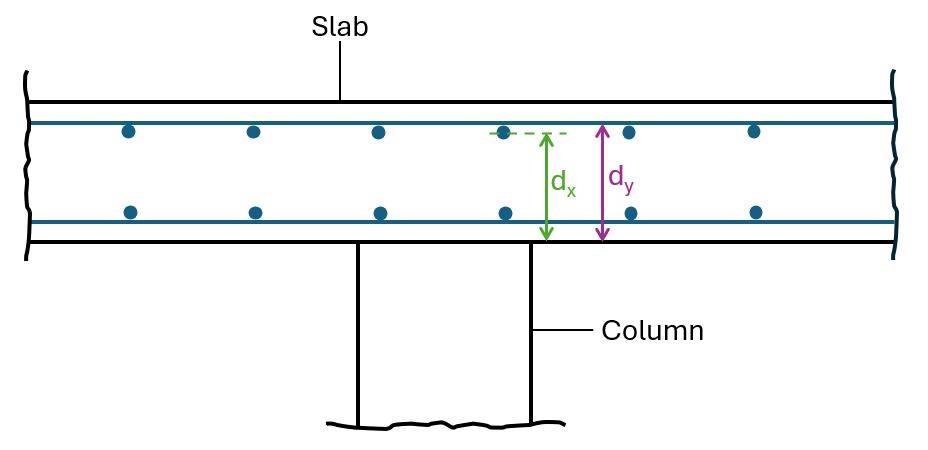
| Depth of reinforcement in x-direction | $d_x = t_p – c – d_{s.y} – \frac{d_{s.x}}{2} = 155 mm$ |
| Depth of reinforcement in y-direction | $d_y = t_p – c – \frac{d_{s.y}}{2} = 165 mm$ |
| Effective depth of slab | $d_{eff} = d = \frac{d_x + d_y}{2} = 160 mm$ |
Next, the shear force/stress of the slab can be reduced with a factor $\beta$. This $\beta$ factor is calculated with formulas EN 1992-1-1 (6.39) – (6.46).
If the columns are not used to stabilize the structure approximate values for $\beta$ from EN 1992-1-1 Figure 6.21N can be used. In our structure there are no shear walls and therefore the columns are used as frame action to stabilize the structure. However, we’ll simplify in this tutorial. Usually, a structure like this has shear walls and therefore, we’ll use EN 1992-1-1 Figure 6.21N to determine $\beta$.
For the center column EN 1992-1-1 Figure 6.21N recommends a value of:
$$\beta = 1.15$$
The reduced shear stress is calculated as:
$$\tau_{Ed} = \beta \cdot \frac{V_{Ed}}{u \cdot d}$$
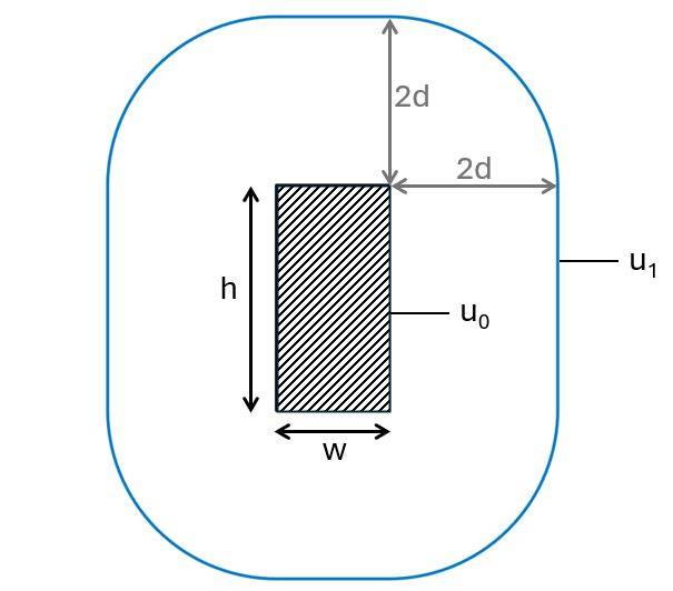
Where u is calculated as the perimeter of the column u0 for verification (1) and the perimeter of the column with a distance of 2d (control perimeter = u1) from all of its edges for verification (2).
Punching shear verification at column perimeter
The first check we’ll do is the verification of punching shear at the column perimeter using to EN 1992-1-1 (6.53):
$$\tau_{Ed} = \frac{\beta \cdot V_{Ed}}{u_0 \cdot d} < \tau_{Rd.max}$$
The shear stress is calculated with the following parameters:
| $\beta$ factor | $\beta = 1.15$ |
| Shear force | $V_{Ed} = 964.3 kN$ |
| Column perimeter | $u_0 = 2h + 2w = 1m$ |
| Effective depth | $d = 0.16 m$ |
$$\tau_{Ed} = \frac{\beta \cdot V_{Ed}}{u_0 \cdot d} = 2.08 MPa$$
The shear resistance $\tau_{Rd.max}$ is calculated as (EN 1992-1-1 (6.53)):
$$\tau_{Rd.max} = 0.5 \cdot \nu \cdot f_{cd}$$
With,
| Strength reduction factor for concrete cracked in shear (EN 1992-1-1 (6.6)) | $\nu = 0.6 \cdot (1- \frac{f_{ck}}{250}) = 0.528$ |
| Design compression strength of concrete C30 | $f_{cd} = 20.69 MPa$ |
Design shear punching shear resistance $\tau_{Rd.max}$ (EN 1992-1-1 (6.53)):
$$\tau_{Rd.max} = 0.5 \cdot \nu \cdot f_{cd} = 5.46 MPa$$
Utilization:
$$\eta = \frac{\tau_{Ed}}{\tau_{Rd.max}} = 0.38 < 1$$
This means that the first check verifies. 👍✅
ULS Punching Shear Verification Without Shear Reinforcement (EN 1992-1-1 6.4.4)
Next, we’ll check if punching shear reinforcement is required.
As a first step, we’ll calculate the shear stress at the control perimeter u1:
$$\tau_{Ed} = \frac{\beta \cdot V_{Ed}}{u_1 \cdot d}$$
The shear stress is calculated with the following parameters:
| $\beta$ factor | $\beta = 1.15$ |
| Shear force | $V_{Ed} = 964.3 kN$ |
| Control perimeter | $u_1 = 2h + 2w + 2 \pi \cdot 2 \cdot d = 3.01 m$ |
| Effective depth | $d = 0.16 m$ |
This leads to a shear stress of:
$$\tau_{Ed} = \frac{\beta \cdot V_{Ed}}{u_1 \cdot d} = 0.69 MPa$$
Next, we’ll calculate the punching shear resistance $\tau_{Rd.c}$:
| EN 1992-1-1 (6.47) | $k = min(1+ \sqrt{\frac{200}{d}}; 2) = 2$ |
| Bonded tension steel (x-direction) | $\rho_x = \frac{A_{s.x}}{d_x \cdot a_x} = 0.0051$ |
| Bonded tension steel (y-direction) | $\rho_y = \frac{A_{s.y}}{d_y \cdot a_y} = 0.0048$ |
| EN 1992-1-1 (6.47) | $\rho = min(\sqrt{\rho_x \cdot \rho_y}; 0.02) = 0.0049$ |
| EN 1992-1-1 (6.47) | $k_1 = 0.1$ |
| EN 1992-1-1 (6.3N) | $\nu_{min} = 0.035 \cdot k^{3/2} \cdot f_{ck}^{1/2} = 0.54 MPa$ |
| Recommended value. Confirm with National Annex. | $C_{Rd.c} = \frac{0.18}{\gamma_c} = 0.124$ |
Design punching shear resistance (EN 1992-1-1 (6.47)):
$$\tau_{Rd.c} = C_{Rd.c} \cdot k \cdot (100 f_{ck})^{1/3} = 0.60 MPa$$
Minimum requirement (EN 1992-1-1 (6.47)):
$$\tau_{Rd.c} > \nu_{Rd.c.min} = \nu_{min} = 1$$
Utilization:
$$\eta = \frac{\tau_{Ed}}{\tau_{Rd.c}} = 1.13 > 1.0$$
Punching shear without shear reinforcement does not verify and we will therefore add punching reinforcement and follow EN 1992-1-1 6.4.5.
ULS Punching Shear Verification With Shear Reinforcement (EN 1992-1-1 6.4.5)
Detailing requirements for punching shear reinforcement are given in EN 1992-1-1 9.4.3.
Before detailing the reinforcement we need to calculate the perimeter uout where no shear reinforcement is required (EN 1992-1-1 (6.54)):
$$u_{out} = \frac{\beta \cdot V_{Ed}}{\tau_{Rd.c} \cdot d} = 3.42 m$$
We’ll use the following punching reinforcement layout. 👇👇
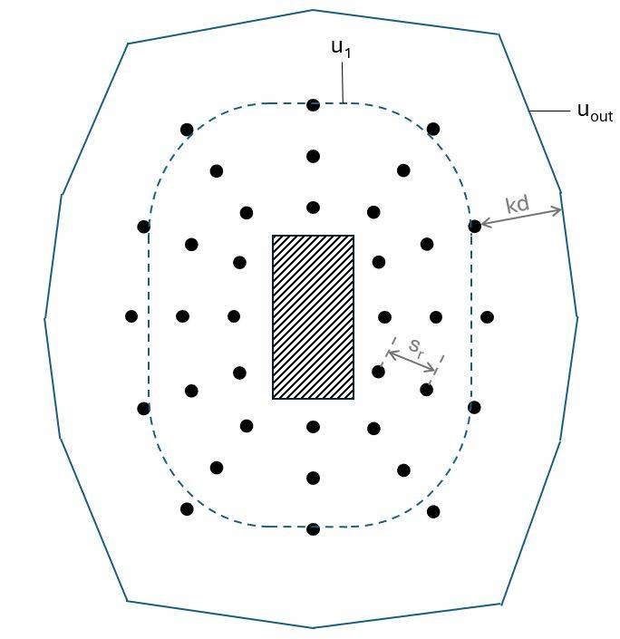
| Number of shear reinforcement legs in radial direction | $n_p = 3$ |
| Radial spacing of perimeters of shear reinforcement | $s_r = 0.4 \cdot d = 64 mm$ |
| Effective design tensile strength of reinforcement (EN 1992-1-1 (6.52)) | $f_{ywd.ef} = min((250 + 0.25 \cdot d/mm) N/mm^2; f_{yd}) = 290 MPa$ |
| Control perimeter where shear reinforcement is not required | $u_{out} = 3416 mm$ |
| Number of reinforcement lines | $n_1 = 12$ |
| Angle of one perimeter of shear reinforcement around the column | $\alpha = 90 deg$ |
| Rebar diameter | $d_{s.s} = 10 mm$ |
| Area of one perimeter of shear reinforcement around the column | $A_{sw} = \pi \cdot (\frac{d_{s.s}}{2})^2 \cdot n_1 = 942.5 mm^2$ |
Design punching shear resistance stress (EN 1992-1-1 (6.52)):
$$\tau_{Rd.cs} = 0.75 \cdot \tau_{Rd.c} + 1.5 \cdot 0.67 \cdot A_{sw} \cdot f_{ywd.ef} \cdot \frac{1}{u_1 \cdot d} \cdot sin(\alpha) = 1.03 MPa$$
Design punching shear resistance force:
$$V_{Rd.cs} = \frac{\tau_{Rd.cs} \cdot u_1 \cdot d}{\beta} = 430.07 kN$$
Utilization:
$$\eta = \frac{V_{Ed}}{V_{Rd.cs}} = 0.67 < 1.0$$
The verification for punching shear with shear reinforcement verifies.
Conclusion
Et voila, the slab is verified and dimensioned for the highest punching shear force. 💯💯
If you are new to structural design, then check out more of our design tutorials where you can learn how to design elements such as: 👇👇
But now, I would like to hear from you: Are you designing a reinforced concrete slab for a uni project? Or are you renovating your own house? Tell us a bit about the structure, as we all want to learn from each other.✍️