King Post Truss: Mastering The Art of Its Design
Are you building a small shed or timber roof for your house, but you’re not sure which type of truss will be best?
The truss is a crucial component of the roof and will affect the overall look and strength of a building, but it’s challenging to decide if a King Post Truss, a Queen Post Truss or maybe a Fink truss is the right choice for the project.
In this blog post, we’ll take a closer look at King Post Trusses and explain their key features, benefits, and common uses.
We’ll also go through a calculation example, step-by-step.
By the end, you’ll better understand whether a king post truss is the right choice for your roof.
Alright, let’s talk KING POST TRUSSES. 🚀🚀
What Is a King Post Truss?
A king post truss is a structural system mainly used in roof construction. It consists of two angled rafters, a central vertical post (“king post”), the bottom chord, and two diagonals connecting the rafter with the bottom chord. It is commonly used in residential and small commercial buildings, such as barns, sheds, and small churches.
The difference between a king post truss and a queen post truss is that the first has just one central vertical post, while a queen post truss has two.
That means queen post trusses can span longer distances and are better for longer spans.
Let’s have a look at the King Post Truss and its members.
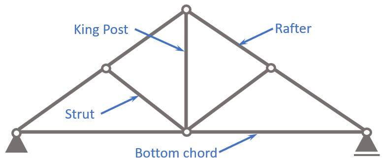
- Rafter
- King Post
- Strut/Diagonal
- Bottom chord
What is the King Post Truss used for?
King Post trusses are mainly used as roof structures of
- Sheds
- in general, for roof structures with smaller spans in buildings.
In most cases, timber is the main material for King post trusses, however steel could also be an option.
Let’s look at the static system to get a better understanding of the structural behaviour of the King Post Truss.🚀🚀
Static System
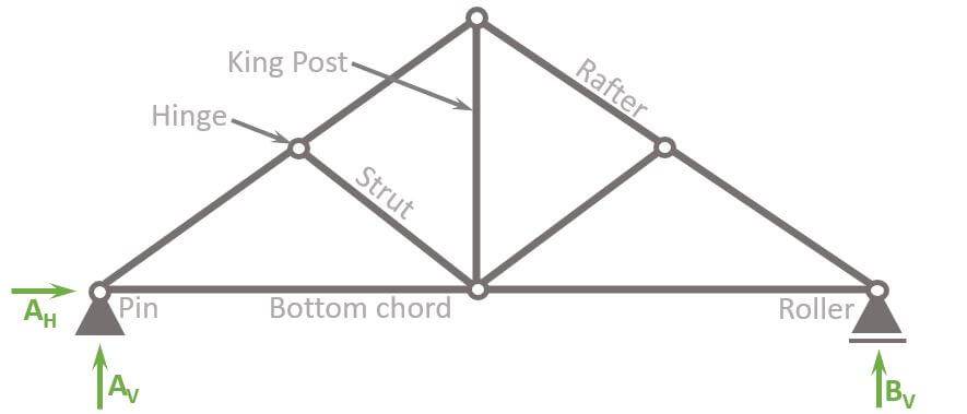
The static system of the King post truss is characterized by having
- hinge connections at all nodes
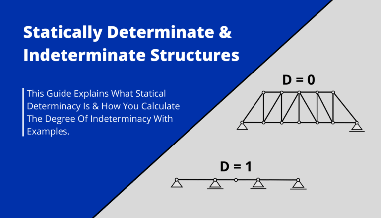
- a pin and roller support, which makes the system statically determinate. Therefore, the internal forces can be calculated with the 3 equilibrium equations.
Hinges
Most truss structures are designed with hinge connections, mainly due to 2 reasons:
- Easier to calculate: Trusses with hinge connections make the structure statically determinate, which means that the internal forces can be calculated by hand. Especially until advanced Finite element software programs weren’t widely available, this was the main reason for using hinge connections. If fixed connections are used, but no software is available, advanced methods like the method of consistent deformation can be used. However, these methods are complicated and susceptible to calculation failures.
- Cost: Hinge connections are cheaper to build than fixed connections.
It definitely makes sense to be aware of the differences of a truss with hinges and fixed connections. In the picture below, you can see the “normal” Pratt truss with hinge connections.
We summarize the characteristics of the truss with fixed connections a bit further below.
Characteristics
Loads
In most cases, the King post truss is used as a roof structure, where dead. snow, wind and live loads are applied on the top or rafters.
Support types
1 Pin and 1 Roller support
Reactions
Pin support: Horizontal AH and vertical reaction force AV
Roller support: Vertical reaction force BV
Connection types
Hinge connections: Moment is 0 in hinge connections.
King Post Truss with fixed connections
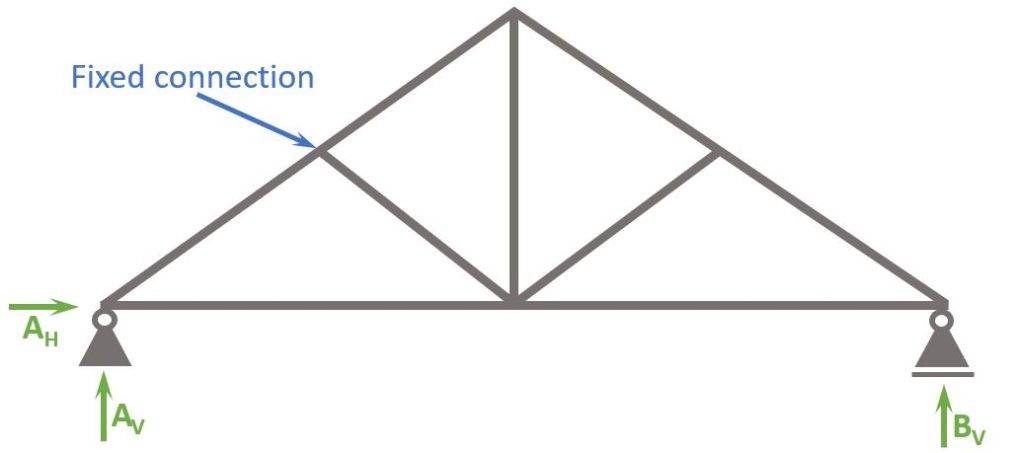
The King post truss with fixed connections has the following differences to hinge connections:
- Bending moments in the connections
- More rigidity -> more robustness
- Smaller vertical deflection
King Post Truss with fixed and hinge connections
The most realistic static system is actually a mix of fixed and hinge connections.
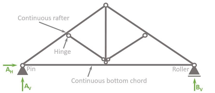
So why is this the most realistic static system?
It’s because usually the rafters and bottom chords are delivered in one piece, meaning that they are constructed continuous and the struts are attached to them.
The rafters basically turn into a 2-span continuous beam, which means that the static system is no longer statically determinate.
This means that advanced methods with FE programs need to be used to calculate the internal forces like Moment, Normal and Shear forces.
Alright, now that we have learned how to set up our static system, we are ready to calculate the internal compression and tension forces of the statically determinate truss.🎉🎉
King Post Truss Analysis
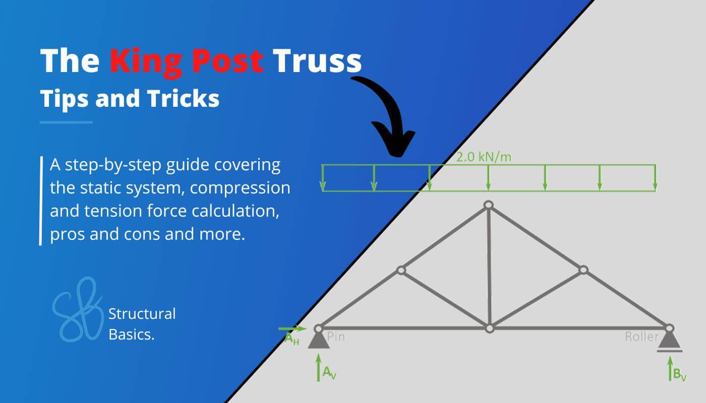
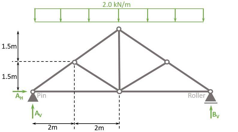
Let’s say our King Post Truss is a roof structure. Therefore, the truss is exposed to the snow load only on the rafters.
We also simplify and say that the load is 2 kN/m. This equals a snow load of 1 kN/m2 and a truss spacing of 2m. Check out this article to learn more about the snow load.
$$1 kN/m^2 \cdot 2m = 2 kN/m$$
Before we start with the calculations, let’s give the nodes 🔵 and bars 🔴 some indices, so the identification is easier later in the internal force calculation.
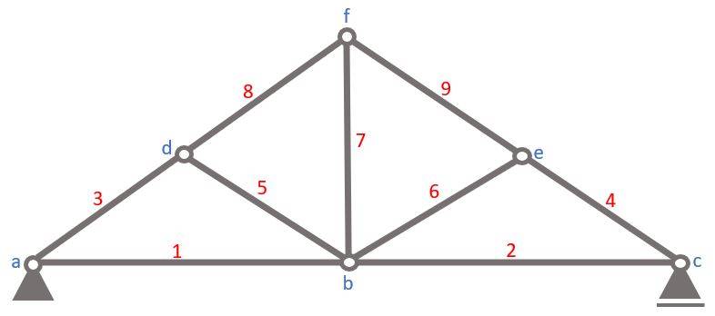
To calculate the compression and tension forces of the truss members with the 3 equilibrium equations, we do another approximation.
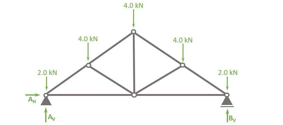
The Line load of 2 kN/m is approximated as point loads⬇️ in the nodes, because otherwise the rafter and bottom chord members would be beams instead of bars, which makes the calculation a lot more difficult.
The point load applied to nodes (a) and (c) is calculated as
$$2 kN/m \cdot 1m = 2.0 kN$$
❗But be careful. The point loads are only transformed like this for the snow load. Dead, wind and live load are applied differently. Check out our article about how to apply loads to roofs.
The point loads applied to nodes (d) and (e) are calculated as
$$2 kN/m \cdot 2m = 4 kN$$
and the point load applied to (f) is calculated as
$$2 kN/m \cdot 2m = 4 kN$$
Let’s calculate. 🚀🚀
Calculation of Reaction Forces
As the structure is statically determinate, the reaction forces can be calculated with the 3 Equilibrium equations.
In our case, we are calculating the support forces AH, AV and BV.
$\sum H = 0: A_H = 0$
$\sum V = 0: A_V + B_V \, – 2 \cdot 2 \, \mbox{kN} \, – 3 \cdot 4 \, \mbox{kN} = 0 $ -> $V_a = V_b = \frac{2 \cdot 2 + 3 \cdot 4}{2} \mbox{kN} = 8 \mbox{kN}$
$\sum M = 0: M_a = 0$
Calculation of the internal forces
Node a
Alright, now that we know the reaction forces, we can calculate the normal force of the first bar elements 1 and 4.
To do that, we only look at node 1 and its point loads/normal forces AV, 2 kN, N1 and N3.
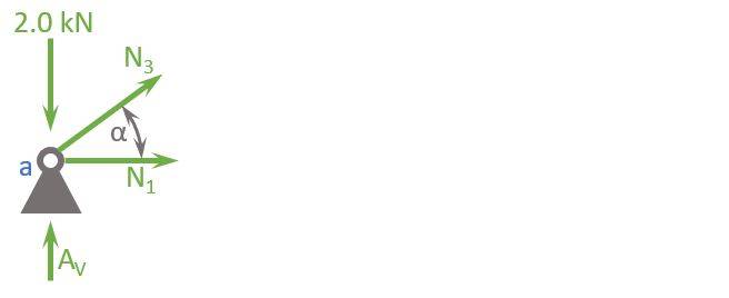
$$ \alpha = atan(\frac{1.5m}{2m}) = 36.9° $$
Vertical Equilibrium:
$$ \sum V = 0: A_v – 2 kN + N_3 \cdot sin(\alpha) = 0$$
Let’s solve that for N3.
$$ N_3 = \frac{2 kN – 8 kN}{sin(\alpha)} = -10 kN$$
Horizontal Equilibrium:
$$ \sum H = 0: N_3 \cdot cos(\alpha) + N_1 = 0$$
Let’s solve that for N1.
$$ N_1 = – N_3 \cdot cos(\alpha) = 8 kN$$
Node d
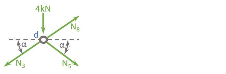
$$ \alpha = 36.9° $$
Horizontal Equilibrium:
$$ \sum H = 0: N_{3} \cos(\alpha) – N_5 \cdot cos(\alpha) – N_8 \cdot cos(\alpha) = 0$$
Let’s solve that for N5 or N8.
$$ N_{5} = N_3 – N_8$$
Vertical Equilibrium:
$$ \sum V = 0: -4 kN – N_3 \cdot sin(\alpha) – N_5 \cdot sin(\alpha) + N_8 \cdot sin(\alpha) = 0$$
Let’s insert N5 from the horizontal equilibrium into the vertical equilibrium equation.
$$-4 kN – N_3 \cdot sin(\alpha) – (N_3 – N_8) \cdot sin(\alpha) + N_8 \cdot sin(\alpha) = 0$$
$$-4 kN – 2 \cdot N_3 \cdot sin(\alpha) + 2 \cdot N_8 \cdot sin(\alpha) = 0$$
Let’s solve that for N8.
$$ N_8 = N_3 + \frac{4 kN}{2sin(\alpha)} = -6.67 kN$$
Now let’s solve N5.
$$ N_{5} = N_3 – N_8 = -3.33 kN$$
Node f
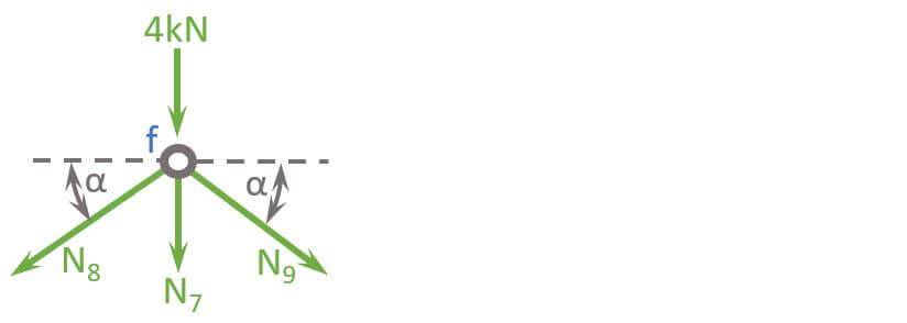
$$ \alpha = 36.9° $$
Vertical Equilibrium:
$$ \sum V = 0: 4 kN + N_7 + N_8 \cdot sin(\alpha) + N_9 \cdot sin(\alpha) = 0$$
Due to symmetry and equal loads N8 = N9.
Let’s solve that for N7.
$$ N_7 = -4 kN – 2 N_8 \cdot sin(\alpha) = 4 kN$$
Well done! Now we have calculated the normal forces of ALL bars.🎉🎉
What all? But we are missing half of the bars.
Yes! But due to symmetry we know that N1 = N2, N3 = N4, N5 = N6, N8 = N9.
So, to summarize it, a normal force diagram helps to understand how the loads travel through the truss.
Normal force diagram
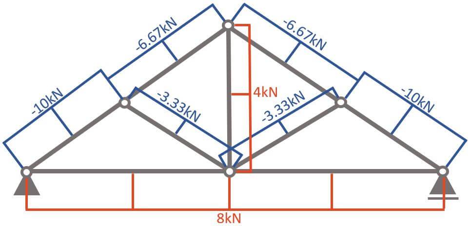
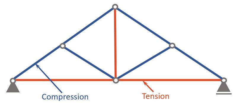
Compression and Tension Members
Now, as you can see in the normal force diagram, some members have a positive (+) and some have a negative (-) normal force.
A negative (-) normal force means that the member is under compression 🔵, while a positive (+) normal force means that the member acts in tension 🔴.
Advantages and Disadvantages
Pros
- Simple design: The king post truss is relatively simple, making it easy to construct. It’s also easy to calculate for engineers.
- Low cost: The simple design of the king post truss also means that it is less expensive to construct than more complex truss designs.
- Suitable for small spans: King post trusses are typically used for small spans of small residential and commercial buildings, such as sheds and barns.
Cons
- Short span: The king post truss is limited to small spans
Conclusion
Now, that you got an overview of the King Post Truss, and how we calculate its internal forces, you can learn about loads, because every truss is exposed to loads.
Because there are always multiple loads acting on King Post Trusses, considering these different loads in the structural design is done by setting up Load Combinations with safety factors.🦺
Once all load cases and combinations are set up, the structural elements can be designed. We have already written a guide on how to design a timber truss. Check it out!
If you want to learn more about trusses, make sure to read our guide on the different types of trusses.
I hope that this article helped you understand the King Post Truss and how to go further from here. In case you still have questions.
Let us know in the comments below ✍️.
King Post Truss FAQ
Both types of trusses have 2 rafters, but the Queen Post Truss has two vertical posts, or “queen posts,” rather than just one. The queen post truss typically spans a longer distance than the King Post Truss.
King post trusses are often used in residential and small commercial buildings, such as barns, sheds, and small churches. They can also be used in construction as decorative elements, such as gazebos and porches.
![The Fink Truss [All YOU Need to Know]](https://www.structuralbasics.com/wp-content/uploads/2022/12/Fink-truss-768x439.jpg)