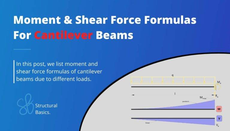
K-Truss [All YOU Need To Know]
Have you driven over or passed by a K-Truss bridge and have wondered how this structural system works? 🤔🤔
And it’s indeed not easy as bridges are one of the most difficult structures engineers design.
But we’ll try to explain the concepts of the k-truss in this article as simple as possible. 👍👍
We’ll explain their key features, benefits, common uses and go through a calculation example, step-by-step.
Alright, let’s talk K-TRUSSES. 🚀🚀
What Is a K-Truss?
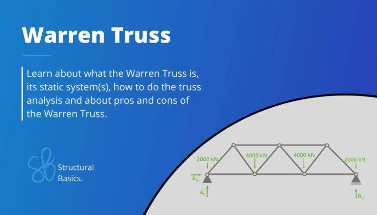
The k truss is a structural system commonly used in engineering projects like bridge structures. It’s characterized by a series of triangles that support the loads of a structure (wind, snow, dead, live load).
Let’s have a look at a visualization of the k-truss and its members.⬇️⬇️
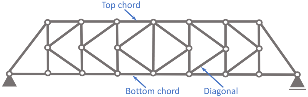
- Top Chord
- Bottom Chord
- Diagonals
What is the K-Truss used for?
K-Trusses are mainly used as bridge structures.
In most cases, steel is the main material, however timber could also be an option.
Let’s look at the static system to get a better understanding of the structural behaviour of the K-Truss.🚀🚀
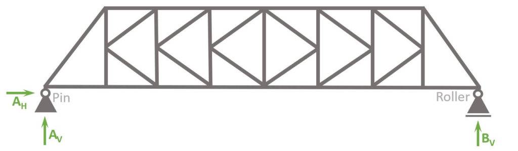
Static System
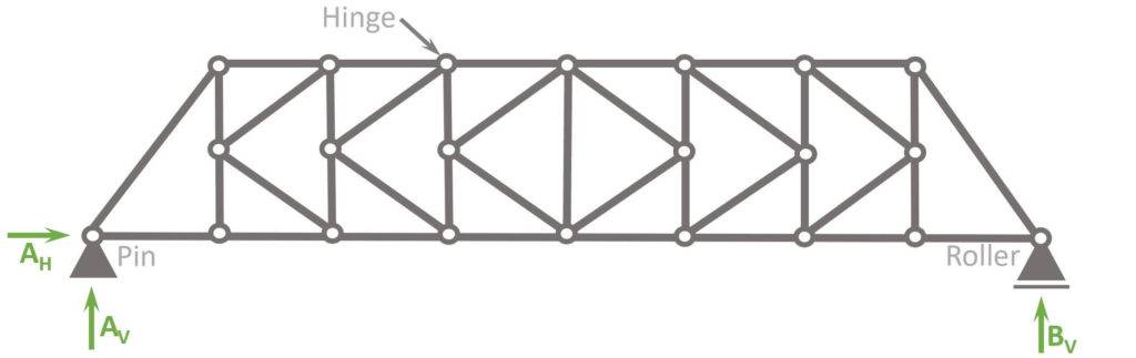
The static system of the k-truss is characterized by having
- hinge connections at all nodes
- a pin and roller support, which makes the system statically determinate. Therefore, the internal forces can be calculated with the 3 equilibrium equations.
Hinges
Most truss structures are designed with hinge connections, mainly due to 2 reasons:
- Easier to calculate: Trusses with hinge connections make the structure statically determinate, which means that the internal forces can be calculated by hand. Especially until advanced Finite element software programs weren’t widely available, this was the main reason for using hinge connections. If fixed connections are used, but no software is available, advanced methods like the method of consistent deformation can be used. However, these methods are complicated and susceptible to calculation failures.
- Cost: Hinge connections are cheaper to build than fixed connections.
It definitely makes sense to be aware of the differences of a truss with hinges and fixed connections. In the picture above, you can see the “normal” k-truss with hinge connections.
We also summarize the characteristics of the truss with fixed connections and a mix of fixed and hinge connections a bit further below.
Characteristics
Loads
In most cases, the k-truss is used as a birdge structure, where dead and traffic loads are applied on the bottom chord.
Support types
1 Pin and 1 Roller support
Reactions
Pin support: Horizontal AH and vertical reaction force AV
Roller support: Vertical reaction force BV
Connection types
Hinge connections: Moment is 0 in hinge connections.
K-Truss with fixed connections
The K-Truss with fixed connections has the following differences to hinge connections:
- Bending moments in the connections
- More rigidity -> more robustness
- Smaller vertical deflection
K-Truss with fixed and hinge connections
The most realistic static system for some bridge structures might actually be a mix of fixed and hinge connections.
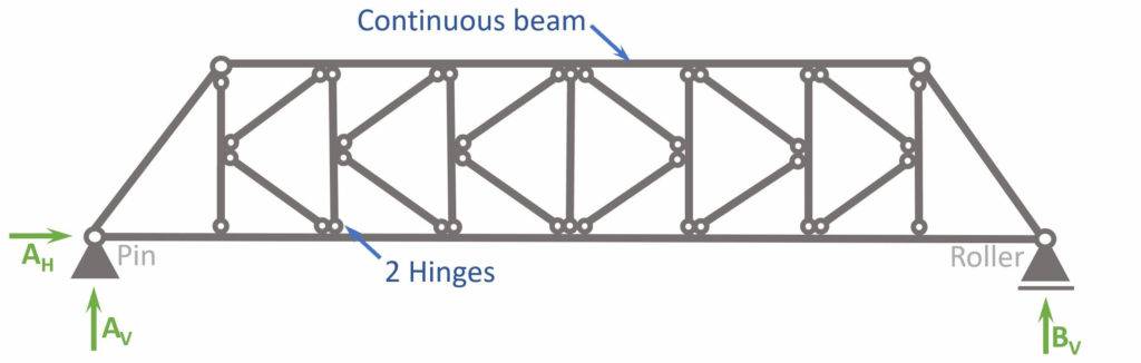
So why is this the most realistic static system?
It’s because the top and bottom chord might be delivered in 1 piece, meaning that they are constructed continuous and the posts and diagonals are attached to them.
The rafters basically turn into a 2-span continuous beam, which means that the static system is no longer statically determinate.
This means that advanced methods with FE programs need to be used to calculate the internal forces like Moment, Normal and Shear forces.
💡💡 However, this depends on whether such long pieces can be delivered and produced. 💡💡
Alright, now that we have learned how to set up our static system, we are ready to calculate the internal compression and tension forces of the statically determinate truss.🎉🎉
K-Truss Analysis
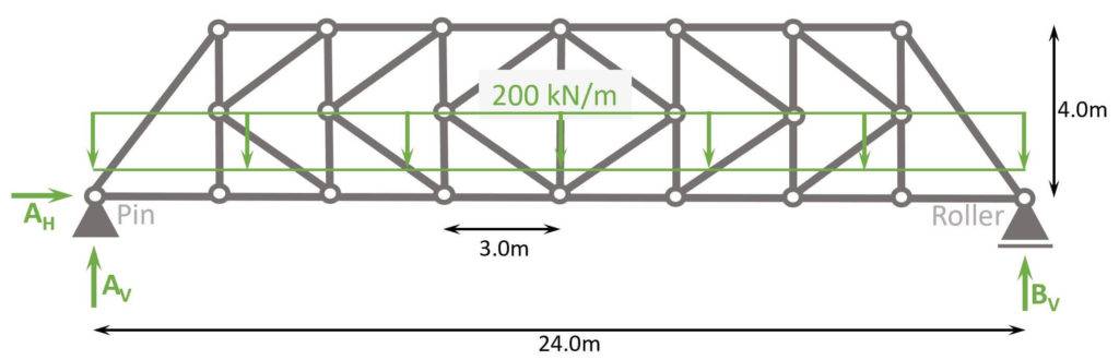
Let’s say our K-Truss is a bridge structure. Therefore, the truss is exposed to the dead load of its own structure on the bottom chord (deck).
We also simplify and say that the design load (Load combination of dead and traffic load) is 200 kN/m.
Check out this article to learn more about the dead load.
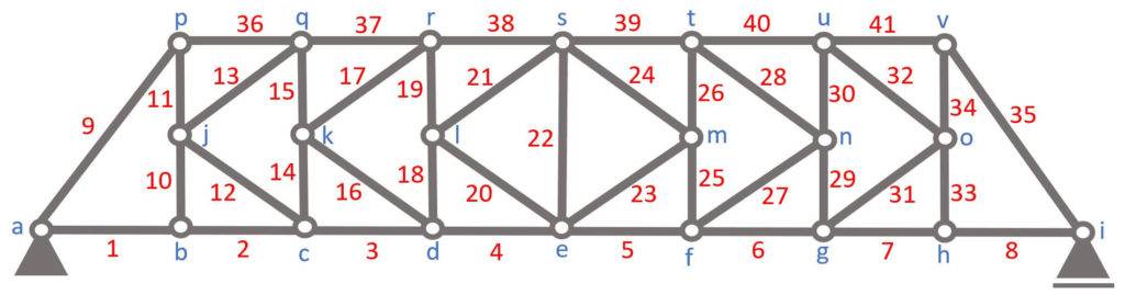
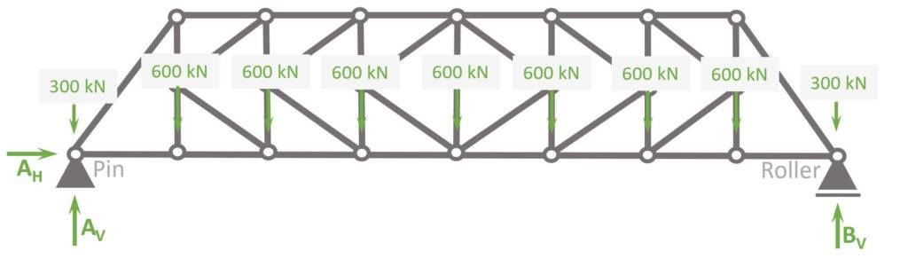
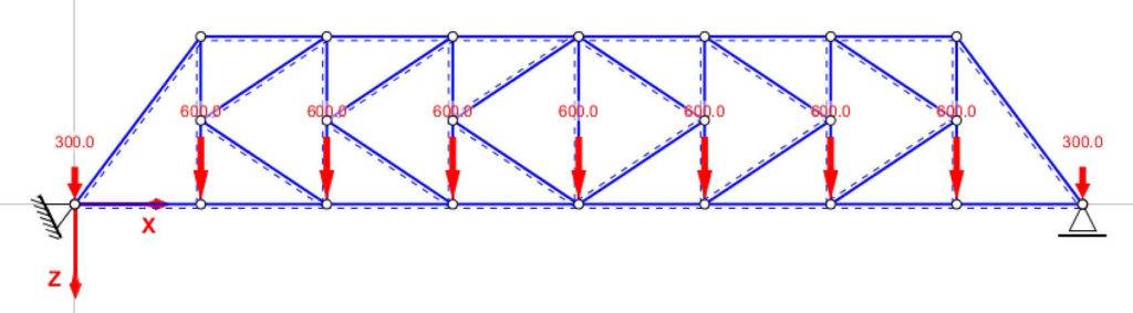
Before we start with the calculations, let’s give the nodes 🔵 and bars 🔴 some indices, so the identification is easier later in the internal force calculation.
To calculate the compression and tension forces of the truss members with the 3 equlibrium equations, we do another approximation.
The Line load of 200 kN/m is approximated as point loads in the nodes, because otherwise the bottom chord members would be beams, which makes the calculation a lot more difficult.
The point load applied to nodes (a) and (i) is calculated as
$$200 kN/m \cdot 1.5m = 300 kN$$
while the point loads applied to nodes (b) – (h) are calculated as
$$200 kN/m \cdot 3m = 600 kN$$
Let’s calculate. 🚀🚀
Calculation of Reaction Forces
As the structure is statically determinate, the reaction forces can be calculated with the 3 Equilibrium equations.
In our case, we are calculating the support forces AH, AV and BV.
$\sum H = 0: A_H = 0$
$\sum V = 0: A_V + B_V \, – 2 \cdot 300 \, \mbox{kN} \, – 7 \cdot 600 \, \mbox{kN} = 0 $ -> $A_V = B_V = \frac{2 \cdot 300 + 7 \cdot 600}{2} \mbox{kN} = 2400 \mbox{kN}$
$\sum M = 0: M_a = 0$
Calculation of the internal forces
Node a
Alright, now that we know the reaction forces, we can calculate the normal force of the first bar elements 1 and 9.
To do that, we only look at node (a) and its point loads/normal forces AV, 300 kN, N1 and N9.
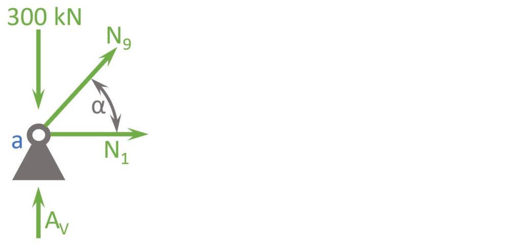
$$ \alpha = atan(\frac{4m}{3m}) = 53.13° $$
Vertical Equilibrium:
$$ \sum V = 0: A_v – 300 kN + N_9 \cdot sin(\alpha) = 0$$
Let’s solve that for N9.
$$ N_3 = \frac{300 kN – 2400 kN}{sin(\alpha)} = -2625 kN$$
Horizontal Equilibrium:
$$ \sum H = 0: N_9 \cdot cos(\alpha) + N_1 = 0$$
Let’s solve that for N1.
$$ N_1 = – N_9 \cdot cos(\alpha) = 1575 kN$$
Node b
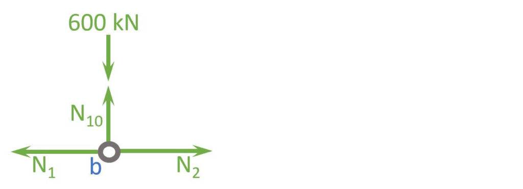
Horizontal Equilibrium:
$$ \sum H = 0: N_{1} – N_2 = 0$$
Let’s solve that for N2.
$$ N_{2} = N_1 = 1575 kN$$
Vertical Equilibrium:
$$ \sum V = 0: N_{10} – 600 kN = 0 $$
$$N_{10} = 600 kN$$
Node p
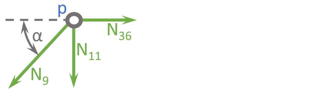
$$ \alpha = 53.13° $$
Vertical Equilibrium:
$$ \sum V = 0: N_{11} + N_9 \cdot sin(\alpha) = 0$$
Let’s solve that for N11.
$$ N_{11} = -N_9 \cdot sin(\alpha) = 2100 kN$$
Horizontal Equilibrium:
$$ \sum H = 0: N_{36} – N_9 \cdot cos(\alpha) = 0$$
Let’s solve that for N36.
$$ N_{36} = N_{9} \cdot cos(\alpha) = – 1575 kN$$
Node j
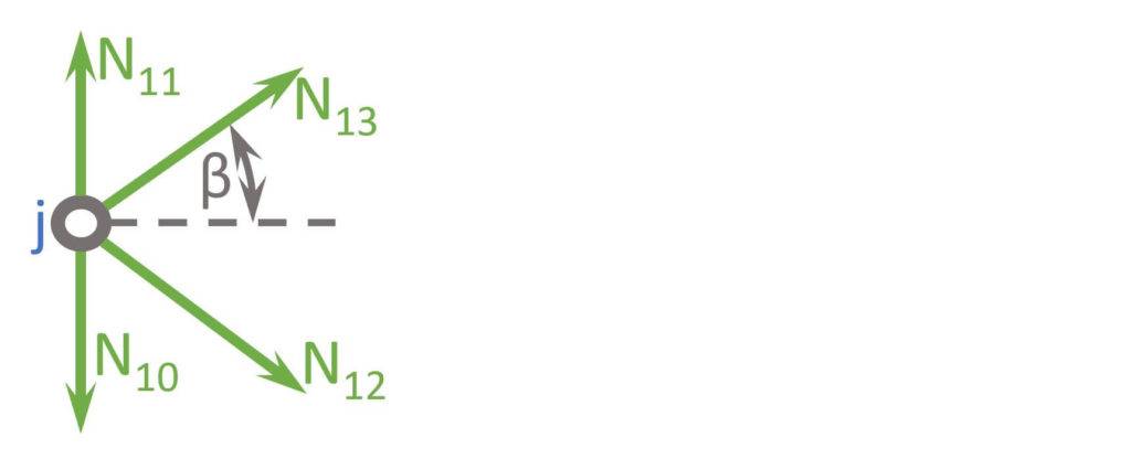
$$ \beta = atan(\frac{2m}{3m}) = 33.69° $$
Horizontal Equilibrium:
$$ \sum H = 0: N_{13} \cdot cos(\beta) + N_{12} \cdot cos(\beta) = 0$$
Let’s solve that for N13.
$$ N_{13} = -N_{12}$$
Vertical Equilibrium:
$$ \sum V = 0: N_{11} – N_{10} + N_{13} \cdot sin(\beta) – N_{12} \cdot sin(\beta) = 0$$
Let’s insert N13 into that equation.
$$ N_{11} – N_{10} – 2 N_{12} \cdot sin(\beta) = 0$$
$$ N_{12} = \frac{N_{11} – N_{10}}{2 sin(\beta)} = 1352.1 kN$$
$$N_{13} = – N_{12} = -1352.1 kN$$
Alright, i think you understood the principle. This can be continued for nodes c, d, e, k, l, q, r and s to calculate the normal forces of the other bars.
💡💡 Due to symmetry of the truss and loads, the right half of bars has the same normal forces as their corresponding bar on the left side.
Now, a way to speed up the calculation is utilizing a FE program, which I did for this k-truss.
I used the free analysis software StaR2 to do it.
❗❗ However, I only recommend using a software if you can confortbly calculate the normal forces yourself and you are aware of the difference of hinge and moment stiff connections, roller and pin supports. Wrong definitions in the model can lead to wrong results. So be careful here!
So, to summarize it, a normal force diagram helps to understand how the loads travel through the truss.
Normal force diagram
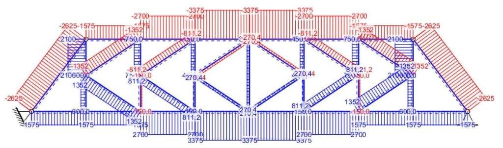
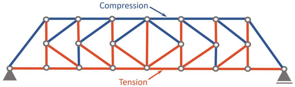
Compression and Tension Members
Now, as you can see in the normal force diagram, some members have a positive (+) and some have a negative (-) normal force.
On this blog we always use 🔵 for compression forces and 🔴 for tension forces. However, in the software that generated the normal force diagram it’s the other way around.
A negative (-) normal force means that the member is under compression 🔵, while a positive (+) normal force means that the member acts in tension 🔴.
Advantages and Disadvantages
Pros
- Buckling: Smaller risk for buckling as elements are shorter than in other truss structures
- Lightweight structural system for longer spans
Cons
- Connections: More connections required than for other truss structures as k-trusses generally have more elements.
- Construction time: More connections and shorter elements also lead to a longer construction time
Conclusion
Now, that you got an overview of the K-Truss, and how we calculate its internal forces, you can learn about loads, because every truss is exposed to loads.
Because there are always multiple loads acting on K-Trusses, considering these different loads in the structural design is done by setting up Load Combinations with safety factors.🦺
Once all load cases and combinations are set up, the structural elements can be designed. We have already written a guide on how to design a timber truss. Check it out!
If you want to learn more about trusses, make sure to read our guide on the different types of trusses.
I hope that this article helped you understand the K-Truss and how to go further from here. In case you still have questions.
Let us know in the comments below ✍️.
K-Truss FAQ
The pros of a k-truss is its short elements with decreases the risk of buckling and increases the strength. This leads to a very lightweight structure.
However this is also a con, because shorter elements lead to more connections, which increases the construction time.
K-Trusses are mainly used as bridge structures. In most cases, steel is the main material, however timber could also be an option.
![Queen Post Trusses Explained! [2026]](https://www.structuralbasics.com/wp-content/uploads/2023/02/Queen-post-truss-768x439.jpg)
![Understand Bending Moments [Everything YOU Need To Know – 2026]](https://www.structuralbasics.com/wp-content/uploads/2023/05/Bending-moment-768x439.jpg)