Imperfection Loads In Structural Engineering {2025 Guide}
Structures are never perfectly straight or connected to other elements. To account for these deviations of the geometry of columns, beams, walls and slabs, we calculate imperfection loads and include these in the structural calculations.
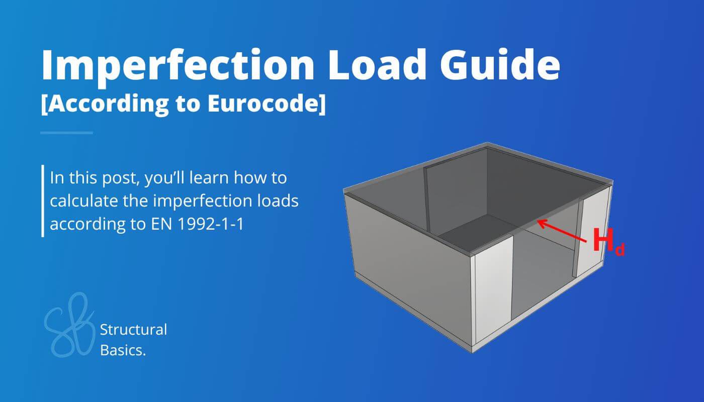
In this article, I’ll show you how to calculate and apply imperfection loads on structures according to EN 1992-1-1.
Let’s get into it. 🚀🚀
What Are Imperfections?
Imperfections of a structure such as slightly inclined columns/walls or deviations of the cross-section in the execution phase happen. No structure is 100% as we calculate it. To account for these deviations of the geometry of the structure, we use imperfection loads.
We calculate the imperfection load according to DS/EN 1992-1-1. And we take them into account in ULS and ALS, but not in serviceability limit states.
Loads from imperfections are calculated for each floor and applied as a horizontal load on the floor diaphragms.
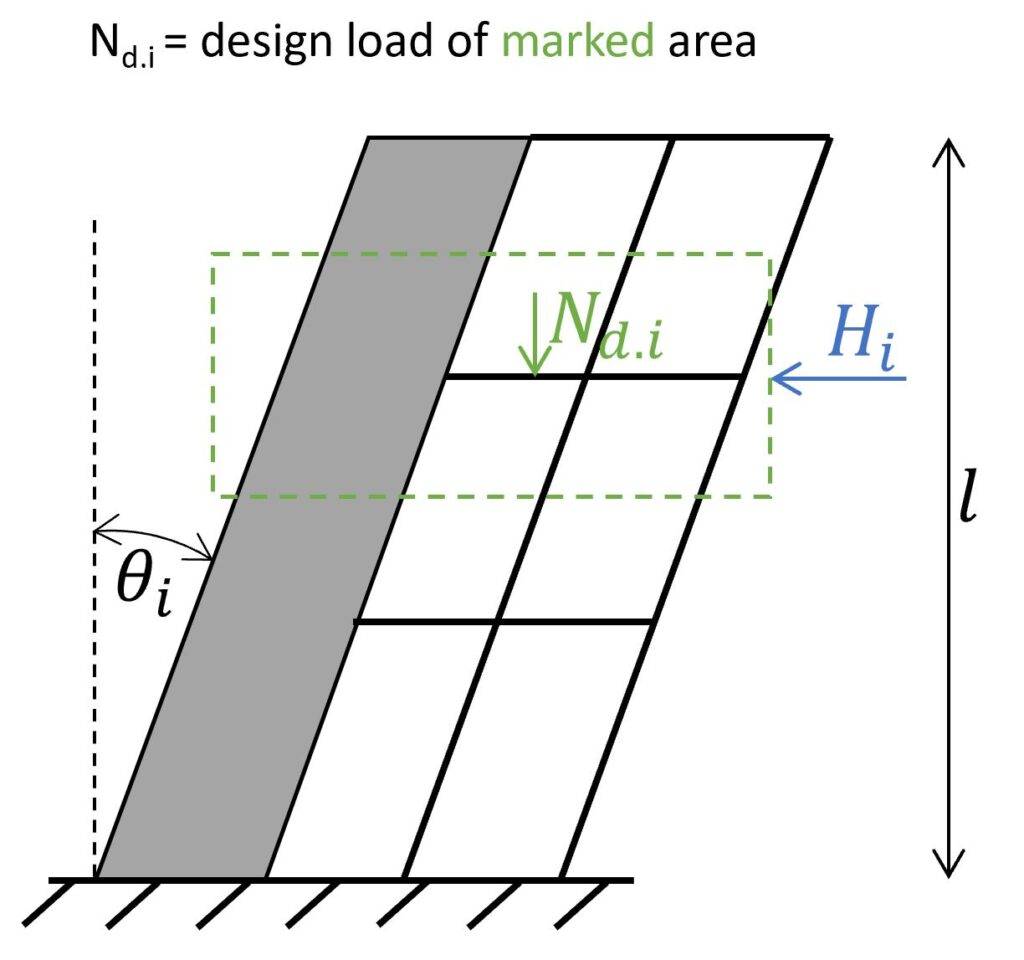
The design value of the horizontal imperfection load per storey, Hd.i, is determined based on the vertical load acting on the slab i:
Imperfection load on floor diaphragm
$$H_{d.i} = \theta_i \cdot N_{d.i}$$
With,
- Nd.i = Vertical design load on floor i in the given load combination, see next figure
- $\theta_i$ = Inclination of the vertical elements, see next figure (calculated in the next section)
Now, let’s look at how to calculate the imperfection load of a specific floor.
Calculation Of Imperfection Loads According To EN 1992-1-1
In this section, we’ll run through the formulas to calculate the imperfection load on a floor. We’ll use the example of the in-situ concrete floor from the next image.
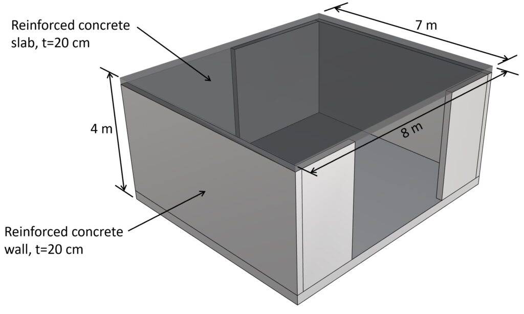
1-storey reinforced concrete structure as example building to showcase the calculation of the geometric imperfection loads.
As shown in the previous section, the imperfection load is calculated as:
Imperfection load on floor diaphragm
$$H_{d.i} = \theta_i \cdot N_{d.i}$$
When we look at the formula, we see that it consists of 2 parameters, the inclination of the vertical elements $\theta_i$, and the vertical design load on the floor.
So, let’s look at both these parameters.
Inclination of the vertical elements θi
The inclination θi, is given by (EN 1992-1-1 (5.1)):
Imperfection load on floor diaphragm
$$\theta_i = \theta_0 \cdot \alpha_{h} \cdot \alpha_m$$
With,
- θ0 = Basic value. EN 1992-1-1 (5.1) recommends a value of 1/200. This means that this value could be defined differently in the National Annex. We’ll use θ0 = 1/200 for our example
- αh = $\frac{2}{\sqrt{l}}; 2/3 \le \alpha_h \le 1$. For l = 4m as the height of the structure, we get $\frac{2}{\sqrt{l}} = 1.0 > 2/3 \rightarrow \alpha_h = 1$
- αm = $\sqrt{0.5 \cdot (1 + 1/m)}$. For m = 5 as the number of vertical members (number of walls in our case) contributing to the horizontal force on the bracing system, we get αm = $\sqrt{0.5 \cdot (1 + 1/m)} = 0.77$.
With these values, the inclination is calculated as:
$$\theta_i = \theta_0 \cdot \alpha_{h} \cdot \alpha_m$$
$$\theta_i = \frac{1}{200} \cdot 1 \cdot 0.77 = 0.39 \%$$
Now, we need to calculate the vertical load on the floor/roof.
Vertical design load on the floor/roof
I usually create a table in Excel with all the quantities like area of floors and walls and length of columns and beams.
| Load | Area load | Height | Length | Area | Total load |
|---|---|---|---|---|---|
| Dead load slab | 25kN/m3 ⋅ 0.2m = 5kN/m2 | – | – | 7m ⋅ 8m = 56m2 | 280 kN |
| Dead load roof layers | 1kN/m2 | – | – | 56m2 | 56 kN |
| Walls | 25kN/m3 ⋅ 0.2m = 5kN/m2 | 2m | 2 ⋅ 7m + 2 ⋅ 2m + 4m = 22m | 2m ⋅ 22m = 44m2 | 220 kN |
| ∑Gk = 556 kN | |||||
| Live load (Cat. H) | 1.0kN/m2 | 56m2 | ∑Qk = 56 kN |
Note, that we only use half of the weight of the walls, because the other half is considered in the imperfection load of the floor below/raft.
Calculation of the imperfection load on the roof floor
We can finally calculate the ULS imperfection load on the roof floor:
Imperfection load on roof diaphragm
$$H_{d.roof} = \theta_i \cdot (1.35 \cdot \sum G_k + 1.5 \cdot \sum Q_k)$$
$$H_{d.roof} = 0.39 \% \cdot (1.35 \cdot 556 kN + 1.5 \cdot 56 kN) = 3.2 kN$$
How To Apply The Imperfection Loads On Floor Diaphragms
The ULS imperfection load is used in the stability analysis of the structure due to wind. It’s added to the horizontal wind loads on the roof diaphragm.
When the stability of the structure is verified due to seismic loads, an accidental imperfection load need to be calculated.
Example
Let’s say:
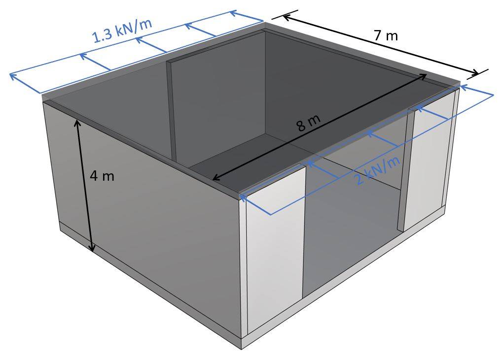
- the design wind load of area D is calculated as 1.0 kN/m2 and of area E as 0.65 kN/m2.
- the wind direction is perpendicular to the facade of width 8m.
- half of the wind load is taken by the roof diaphragm and half is transferred to the raft.
These assumptions lead to a wind line load of area D of 1.0 kN/m2 ⋅ 4m/2 = 2 kN/m and area E of 0.65 kN/m2 ⋅ 4m/2 = 1.3 kN/m. When we design and verify the diaphragm, we would also need to add the imperfection load and distribute it as a line load. But I want to show you how to add the imperfection load to the stability analysis.
When verifying the stability, the line loads travel to the shear walls, which are placed in the same direction as the load. For this type of building, we can assume that half of the load is taken by the left wall and half by the right wall.
The total point load due to wind on the walls/diaphragm is calculated as:
Total wind load on diaphragm/walls
$$W_{d.roof} = (2 kN/m + 1.3 kN/m) \cdot 8m = 26.4 kN$$
We add the imperfection load to this wind load. This way, the imperfection load is included in the stability analysis of the shear walls.
Total design load on diaphragm/walls
$$P_{d.roof} = W_{d.roof} + H_{d.roof} = 26.4 kN + 3.2 kN = 29.6 kN$$
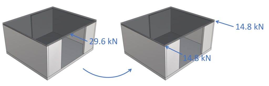
The shear walls can now be designed and verified for the horizontal design load of 14.8 kN, which includes the imperfection load.
Final Words
Et voilà, that’s how we calculate the imperfection load according to Eurocode. 💯💯
As already said, the next step is to verify the stabilizing elements that take up the horizontal loads.
In this article, we made assumptions for the wind load. But if you want to learn how to calculate wind loads on walls according to Eurocode, then check out our step-by-step guide or video tutorial.

Laurin Ernst

![Types of Loads on Beams [Full Guide]](https://www.structuralbasics.com/wp-content/uploads/2022/11/Types-of-loads-on-beams-768x439.jpg)