Impact Loads From Vehicles {Accidental Actions}

When designing a building or structure close to a street, then walls and columns need to be designed for impact loads from vehicles.
In this article, I’ll show you, how to calculate and apply these accidental actions on a building according to Eurocode.
Let’s get into it. 🚀🚀
What Are Impact Loads From Vehicles And When Do You Need To Consider Them?
Impact loads are the representation of the action when a vehicle hits a structure like a building or bridge.
According to EN 1991-1-7 4.2 (1) these actions need to be considered in the structural design by either dynamic analysis or an equivalent static force.
In the structural engineering projects I’ve worked on, we always chose to use an equivalent static force. This is quicker and easier as the load values are given in EN 1991-1-7 Table 4.1 and Table 4.2 for different traffic categories.
In general, we have to differentiate between actions on substructures and superstructures. We’ll explain their difference now.
Impact on supporting substructures
Examples of supporting substructures are according to EN 1991-1-7 4.3.1 (1) are:
- columns and
- walls of bridges or buildings
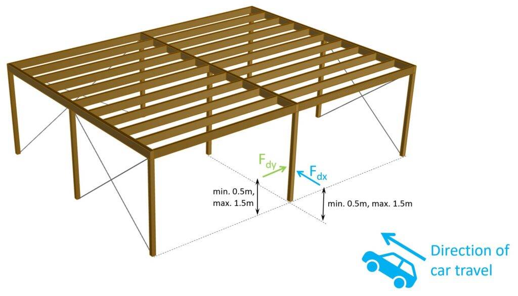
In the structural design, these columns and walls need to be checked for an impact load Fdx in the direction of normal travel and Fdy perpendicular to normal travel. Now, for everyone who isn’t a native English speaker, normal travel means in the direction of the car. Both Fdx and Fdy are defined in EN 1991-1-7 Table 4.1 or in “our table” in the next section.
If we look at the example of a canopy / carport with some columns, Fdx is the load applied in the direction of the car and Fdy perpendicular to this. We’ll look at the precise location of where the load has to be applied in one of the next sections.

Impact on superstructures
A superstructure is mainly referred to bridges. Part of bridge superstructures are the deck, cables, arches, etc. Basically anything above the substructure which are supports like abutments, piers and bearings.
Impact loads on superstructures result for example from accidents where a truck is taller than the opening of a frame bridge and drives into it. You probably have already seen such an incident?
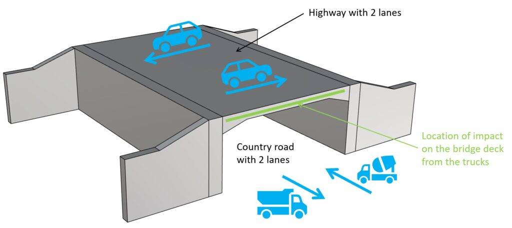
In the structural design, the bridge (its static and structural system) needs to be verified for an impact load Fdx in the direction of normal travel of the vehicle. The value of Fdx is defined in EN 1991-1-7 Table 4.2 or in “our table” in the next section.
How to apply impact loads on walls and columns
According to EN 1991-1-7 4.3.1 (3) the impact loads Fdx and Fdy should be applied at a height of 0.5m to 1.5m above the level of the pavement and the recommended application area is a = 0.5m in height and 1.5m in width.
Now, columns are of course in most cases not 1.5m wide, then the load is applied on the width of the column. Or, because columns are designed as beams, the load can be applied as a point load or as a line load with width (=a) =0.5m.
Let’s visualize these loads in 3D.
Impact loads on columns

Impact loads on walls
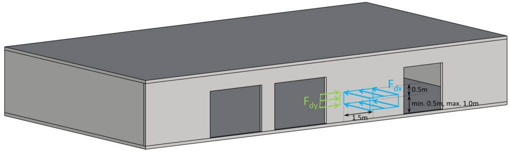
Fdx is applied to the wall as an area load. This helps distribute the load. Also, in case you design the wall with a finite element program using an area load instead of a point load also helps avoid singularities.
The area load is calculated as:
Fdx.a [kN/m2] = Fdx.p [kN] ⋅ w [kN] ⋅ a [kN]
With,
- Fdx.a = The area impact load in direction x
- Fdx.p = The point impact load in direction x defined in the table in the next section
- w = Width of the impact load. In the example above, w = 1.5m
- a = Height of the impact load. In the example above, a = 0.5m
But you should always consider the most critical area. In the example from above, that would be the wall column between the 2 openings. It’s more critical because the cross-section is smaller due to a smaller width.
Values Of Impact Loads According To Eurocode
The equivalent static impact loads defined in Eurocode are summarized in the 2 tables below. Note that these values are from the general Eurocode and could be defined differently in the National Annex of the country the structure is located in.
Impact loads on substructures like columns and walls according to EN 1991-1-7 Table 4.1
| Category of traffic | Force Fdx [kN] | Force Fdy [kN] |
|---|---|---|
| Motorways and country national and main roads | 1000 | 500 |
| Country roads in rural areas | 750 | 375 |
| Roads in urban areas | 500 | 250 |
| Courtyards and parking garages with access to cars (a) / lorries (b) | 50 (a) / 150 (b) | 25 (a) / 75 (b) |
Impact loads on superstructures of bridges according to EN 1991-1-7 Table 4.2
| Category of traffic | Force Fdx [kN] |
|---|---|
| Motorways and country national and main roads | 500 |
| Country roads in rural areas | 375 |
| Roads in urban areas | 250 |
| Courtyards and parking garages | 75 |
Closing
Looking at the values of the impact loads, their influence on the design of structural elements close to a street can be quite significant.
You can check out Dlubal’s article where they show another calculation method which results in smaller impact loads from vehicles.
If you liked this article, then you might also like:

Laurin Ernst