How To Calculate The Peak Velocity Pressure {2026}
The calculation of the peak velocity pressure is the 1st step when calculating the wind load on roofs, walls and bridges. 💨🌬️
In this blog post we show, step-by-step, how to calculate the peak velocity pressure according to Eurocode. 🧮🔢
Before we start calculating anything, let’s start with the question: What do we need the peak velocity pressure for? 🤔🤔
The value of the peak velocity pressure includes many parameters about the location, height of the building and some more. The unit is in $kN/m^2$, and we need the peak velocity pressure to calculate the wind forces which act on roofs and facades/walls.
Let’s get started. 🚀🚀
Process of peak velocity pressure calculation
To calculate the peak velocity pressure, we have to do the following steps. 👇👇
- Height of the structure
- Fundamental value of basic wind velocity vb.0
- Orography factor c0
- Turbulence factor kl
- Density of air $\rho$
- Reference height terrain category II z0.II
- Roughness length z0
- Terrain factor kr
- Turbulence intensity Iv
- Roughness factor cr
- Mean wind velocity vm
- Peak velocity pressure qp
1. Geometry of the structure
As you might have already figured out – I like to use examples. This time, we will calculate the peak velocity pressure for a precast concrete office building. The material does not matter for this calculation. We need the dimensions of the building.

As you can see from the picture, the building has the following dimensions
| Height above ground | z = 17.1m |
2. Fundamental value of basic wind velocity vb.0
According to EN 1991-1-4 1.6.1 the fundamental value of basic wind velocity describes a 10-minute mean value at a height of 10 m above ground and in an open country terrain which includes annual risks and some more parameters.
For the exact definition, you can have a look at the mentioned Eurocode section.
This value must be found in the Nation Annex
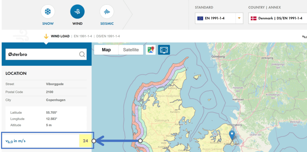
Or: We can also use the wind speed calculator made by Dlubal Software GmbH. Click here to open the online calculator. 👇👇
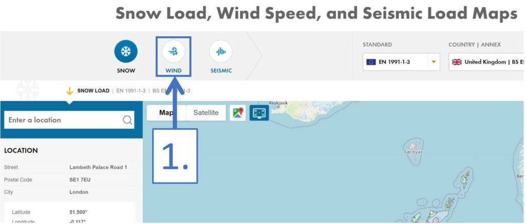
1. Step: Click on the wind icon
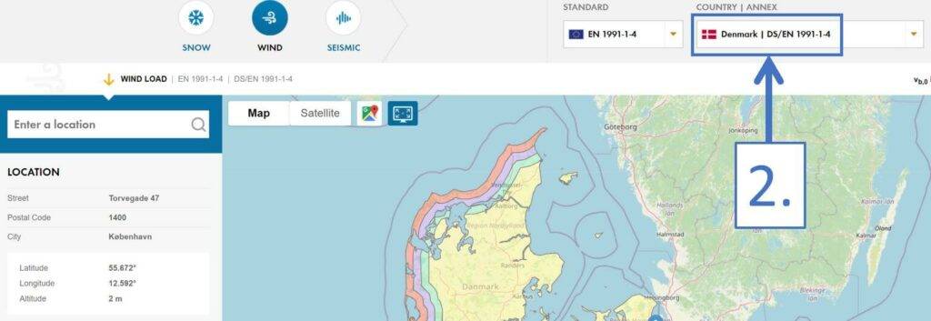
2. Step: Choose your country and national annex
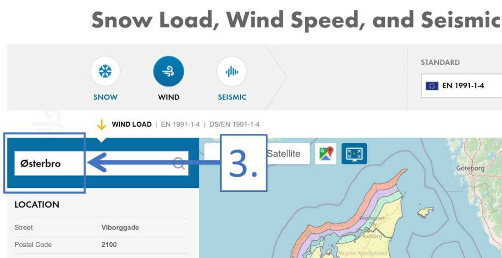
3. Step: Type in the location of the structure
Btw, Østerbro is the district in Copenhagen in which I live. ✌️😄
For an office building located in Copenhagen, Denmark, we get a fundamental value of the basic wind velocity of
$$v_{b.0} = 24 \frac{m}{s}$$
3. Orography factor c0
EN 1991-1-4 4.3.1 (1) recommends the Orography factor to be taken as 1.0.
$$c_{0} = 1.0 $$
❗
This value may be defined differently in the National Annex of your country. So double-check if that is the case.
4. Turbulence factor kl
As for the Orography factor, EN 1991-1-4 4.4 (4.7) recommends also the turbulence factor to be takes as 1.0.
$$k_{l} = 1.0 $$
❗
Again also this value may be defined differently in the National Annex of your country. So double-check if that is the case.
5. Density of air $\rho$
The recommended value for the density of air is given in EN 1991-1-4 4.5 (1) and it is 1.25 kg/m3.
$$\rho = 1.25 \frac{kg}{m^3}$$
6. Reference height Terrain category II z0.II
The reference height of terrain category II is used to calculate the terrain factor kr. The value can be found in EN 1991-1-4 Table 4.1.
$$z_{0.II} = 0.05 m$$
7. Roughness Length z0
The roughness length is also used to calculate the terrain factor kr.
The value depends on the terrain category where our building or structure is located. The value can also be found in EN 1991-1-4 Table 4.1.
In our case, we assume that our office building is located in a suburban terrain with regular cover of buildings.
Therefore, the building falls into terrain category III.
$$z_{0} = 0.3 m$$
8. Terrain factor kr
The formula to calculate can be found in EN 1991-1-4 (4.5).
$$k_{r} = 0.19 \cdot (\frac{z_{0}}{z_{0.II}})^{0.07}$$
Inserting the values of $z_{0.II}$ and $z_{0} $ leads to
$$k_{r} = 0.19 \cdot (\frac{0.3m}{0.05m})^{0.07} = 0.215$$
9. Turbulence Intensity Iv
The turbulence intensity is calculated with EN 1991-1-4 (4.7).
$$I_{v} = \frac{k_{1}}{c_{0} \cdot ln(\frac{z}{z_{0}})}$$
leading to
$$I_{v} = \frac{1.0}{1.0 \cdot ln(\frac{17.1m}{0.3m})} = 0.247$$
10. Roughness factor cr
The roughness factor is calculated with EN 1991-1-4 (4.4)
$$c_{r} = k_{r} \cdot ln(\frac{z}{z_{0}})$$
leading to
$$c_{r} = 0.215 \cdot ln(\frac{17.1}{0.3m}) = 0.871$$
11. Seasonal factor cseason
The principle of the seasonal factor is that the wind load can be lowered because the wind is blowing less strong in some months.
In the case that you are designing a temporary structure such as a tent or a canopy that is built for a short time frame and then disassembled after a few weeks, you might be able to use a seasonal factor cseason depending on the months it has to withstand the wind.
When you need to design your structure for the execution phase, then you might also be able to use cseason. We are designing an office building which is NOT temporary and therefore cseason is taken as 1.0 and can be left out of the calculations.
$$c_{season} = 1.0$$
❗
The seasonal factors can be specified in the National Annex in case you are designing a temporary structure.
12. Directional factor cdir
The principle of the directional factor is that the wind is blowing less from certain directions and therefore the peak velocity pressure and then the wind load can be reduced for those directions.
The recommended value for the directional factor is given in EN 1991-1-4 4.2 Note 2 as 1.0.
However, it is also referred to the National annex, which might define cdir.
$$c_{dir} = 1.0$$
In further calculations, cdir is not included because a value of 1.0 is neither increasing nor decrease the peak velocity pressure.
13. Mean wind velocity vm
The mean wind velocity is calculated by EN 1991-1-4 (4.3) as
$$v_{m} = c_{r} \cdot c_{0} \cdot v_{b.0}$$
leading to a mean wind velocity of
$$v_{m} = 0.871 \cdot 1.0 \cdot 24 \frac{m}{s} = 20.9 \frac{m}{s}$$
Finally, we can calculate the peak velocity pressure. 👍👍
14. Peak velocity pressure qp
The mean wind velocity is calculated by EN 1991-1-4 (4.8) as
$$q_{p} = [1 + 7 \cdot I_{v}] \cdot \frac{1}{2} \cdot \rho \cdot v_{m}^2$$
leading to a peak velocity pressure of
$$q_{p} = [1 + 7 \cdot 0.247] \cdot \frac{1}{2} \cdot 1.25\frac{kg}{m3} \cdot (20.9 \frac{m}{s})^2 = 0.746 \frac{kN}{m^2}$$
Summary
For a building with the height of 17.1 m in a suburban area in Copenhagen, Denmark, the wind load can be calculated with a peak velocity pressure of qp = 0.746 kN/m2.
And that is exactly what we did in the following articles: 👇👇
- Wind load calculation of walls
- Wind load calculation of a flat roof
- Wind load calculation of a pitched roof
- Wind load calculation of an arched structure
Peak Velocity Pressure FAQ
You calculate the peak velocity pressure with formulas from Eurocode EN 1991-1-4 and its national annex.
The higher a structure or building is, the greater the peak velocity pressure. However, the calculated peak velocity pressure or wind load can often be reduced by CFD calculations or a wind tunnel test. But this is expensive.
![Vertical Load Transfer In Structural Engineering [2026]](https://www.structuralbasics.com/wp-content/uploads/2024/09/Vertical-load-transfer-1-768x439.jpg)


![Load Combination Generator [How-To Guide]](https://www.structuralbasics.com/wp-content/uploads/2023/02/load-combination-generator-768x439.jpg)
As a semi-retired ( but still dabbling) UK Engineer I’m far more familiar with the “simpler” British Standard COP’s. Nevertheless I wanted to teach myself the Eurocode approach but was finding the Eurocodes a bit more difficult to follow until I stumbled across your excellent videos on Youtube. The videos and hardcopy notes are so clear so my thanks to all those responsible for the time taken to create them. I real benefit for my ageing brain!
Hi Trevor,
Thanks for the great feedback!
It’s great to hear that you think that the videos and posts are easy to understand. That’s the goal with it.
Best regards,
Laurin