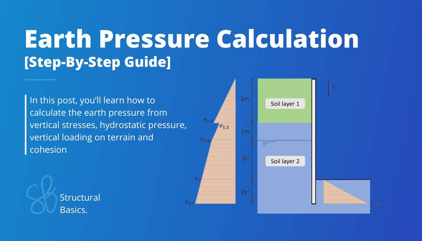
Earth Pressure Calculation On Underground Structures [2025]
The earth pressure acts on underground structures like basement walls, retaining walls and sheet piles.
When designing these structures, the lateral earth pressure always has to be considered.
In this article, I’ll show you how I, as a structural engineer, calculate the earth pressure.
Before getting into it. If you want to learn everything you need to know about other loads like the snow load, wind load, dead load, live load or the imperfection load, then I invite you to join my free 8-day email course about loads.
Let’s get into it.
What Is The Earth Pressure?
The earth pressure is the load/pressure that the weight of the soil and other loads apply in the lateral (horizontal) direction to vertical structures like basement walls or retaining walls.
The earth pressure needs to be considered whenever a structure holds back soil.
Other examples where the earth pressure needs to be considered are:
- sheet piles
- metro stations and
- tunnels
The active earth pressure ea is calculated as
$$e_a = \sigma_v’ \cdot K_a – 2 \cdot c_{ef} \cdot \sqrt{K_a}$$
With,
- σv′ = effective vertical stress (see later section)
- Ka = Rankine active earth pressure (calculated in a later section)
- cef = effective cohesion of soil
In the following sections, we’ll split up the calculation of the earth pressure and cohesion.
The direction of the earth pressure (load) is mostly calculated as a horizontal load.
Other actions on underground structures
The horizontal load on an underground structure is furthermore influenced by:
- hydrostatic water pressure
- level of groundwater
- cohesion
- live load on terrain close to the structure
- multiple soil layers with different soil properties
We’ll show how to calculate these actions also later in this article.
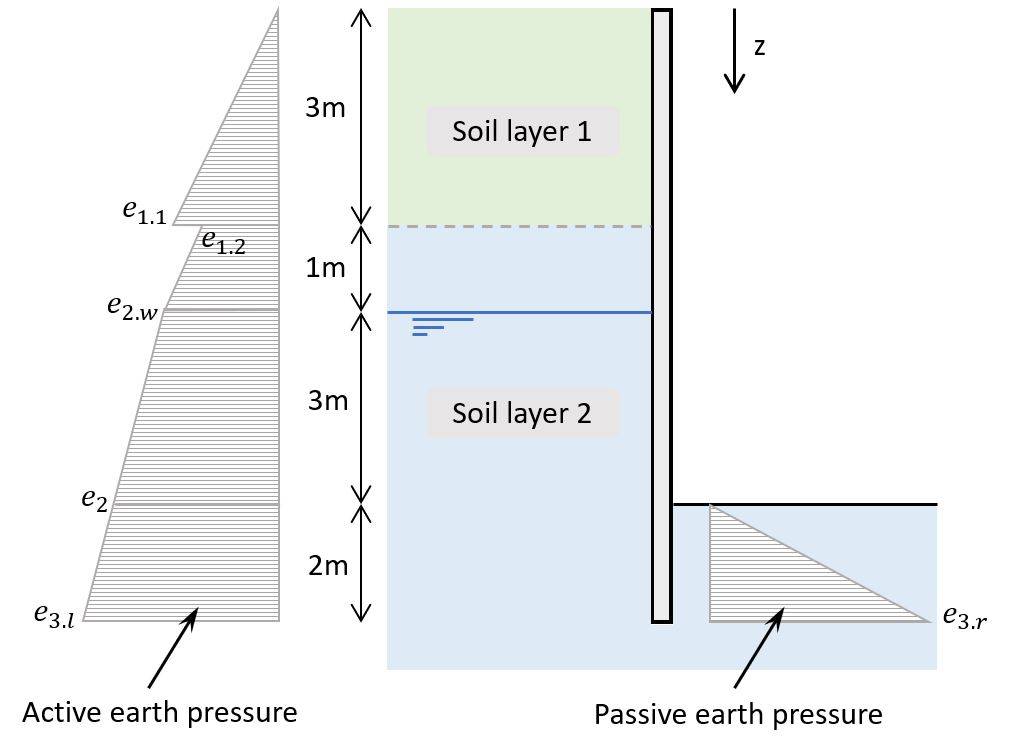
Here’s an example of a possible soil pressure on a retaining wall.
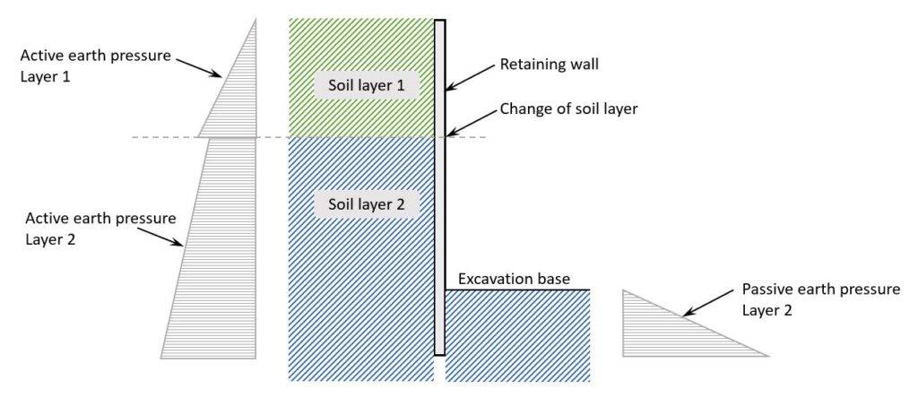
As you can see from the picture above, there are an active and a passive earth pressure acting on the wall.
Active earth pressure
The active earth pressure happens when the wall moves away from the soil. So, when the wall deflects because of the lateral loading.
Passive earth pressure
In the passive condition, the wall is pushed towards the backfill. In general, the passive earth pressure is greater than the active earth pressure.
Process Of Calculating The Earth Pressure & The Total Actions On An Underground Structure Like Retaining Walls
1. Soil properties of the different layers
2. Rankine earth pressure coefficient
3. Effective vertical stresses
4. Rankine active and passive earth pressures
5. Cohesion
6. Hydrostatic water pressure
7. Live load on terrain close to the structure
Calculation Of The Earth Pressure
We split up the calculation of the earth pressure into multiple steps.
This way, it’s easy to follow along. We also use a practical example structure to explain the calculation steps.
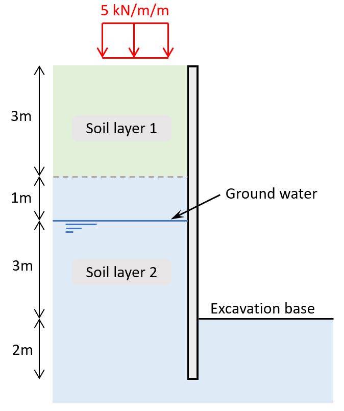
Example structure
Throughout this article, we’ll use the following example wall structure and soil layers to explain the calculation steps.
1. Soil properties of the soil layers
Here are the properties to the 2 soil layers we’ll use in the calculation of the actions on the underground structure.
| Soil layer 1 | Soil layer 2 | |
|---|---|---|
| Unit weight γ | 18 kN/m3 | 20 kN/m3 |
| Effective angle of friction ϕef | 30° | 38° |
| Effective cohesion cef | 3 kPa | 0 kPa |
| Partial factor – angle of friction γϕ (Danish Annex) | 1.2 | 1.2 |
| Partial factor – Effective cohesion γc (Danish Annex) | 1.2 | 1.2 |
The partial factors for angle of friction and effective cohesion are used to calculate the design properties of soil. Note that these values are different for each country, as every country has its own national annex.
| Soil layer 1 | Soil layer 2 | |
|---|---|---|
| Effective angle of friction ϕef | $atan(\frac{tan(30°)}{\gamma_{\phi}}) = 25.7°$ | $atan(\frac{tan(38°)}{\gamma_{\phi}}) = 33.1°$ |
| Effective cohesion cef | $\frac{3 kPa}{\gamma_c} = 2.5 kPa$ | 0 kPa |
2. Rankine earth pressure coefficient
The Rankine earth pressure coefficients are used to calculate the earth pressure for each layer at a depth z.
Rankine active earth pressure coefficient $K_a$
$$K_a = \frac{1 – sin(\phi_{ef})}{1 + sin(\phi_{ef})}$$
Rankine passive earth pressure coefficient $K_p$
$$K_p = \frac{1 + sin(\phi_{ef})}{1 – sin(\phi_{ef})}$$
Now, let’s calculate them for the different layers.
| Soil layer 1 | Soil layer 2 | |
|---|---|---|
| Ka | $\frac{1 – sin(25.7°)}{1 + sin(25.7°)} = 0.4$ | $\frac{1 – sin(33.1°)}{1 + sin(33.1°)} = 0.29$ |
| Kp | $\frac{1 + sin(25.7°)}{1 – sin(25.7°)} = 2.53$ | $\frac{1 + sin(33.1°)}{1 – sin(33.1°)} =3.4$ |
3. Effective stresses
The effective stresses depend on the weight of the soil and are calculated for the depth z as:
$$\sigma_v’ = \gamma \cdot z$$
Where γ is the unit weight of the soil layer above the ground water table. Below the ground water table γ-γw is used respectively.
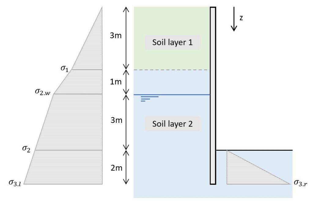
| Depth [m] | σv‘ [kPa] | |
|---|---|---|
| σ1 | 3 | $\gamma_1 \cdot 3m = 54 kN/m^2$ |
| σ2.w | 4 | $\sigma_1 + \gamma_2 \cdot 1m = 74 kN/m^2$ |
| σ2 | 7 | $\sigma_{2.w} + (\gamma_2 – \gamma_w) \cdot 3m = 104 kN/m^2$ |
| σ3.l | 9 | $\sigma_{2} + (\gamma_2 – \gamma_w) \cdot 2m = 124 kN/m^2$ |
| σ3.r | 9 | $(\gamma_2 – \gamma_w) \cdot 2m = 20 kN/m^2$ |
4. Rankine active and passive earth pressures
The rankine active and passive earth pressures are calculated with the vertical effective stresses and the rankine coefficients that we derived in steps #2 and #3.
Rankine active earth pressure
$$e_a = \sigma_v’ \cdot K_a$$
Rankine passive earth pressure
$$e_p = \sigma_v’ \cdot K_p$$
So, let’s calculate the earth pressures for the different depths.
| e [kN/m2] | ||
|---|---|---|
| e1.1 | $\sigma_{1} \cdot K_{a.1}$ | 21.3 |
| e1.2 | $\sigma_{1} \cdot K_{a.2}$ | 15.9 |
| e2.w | $\sigma_{2.w} \cdot K_{a.2}$ | 21.8 |
| e2 | $\sigma_{2} \cdot K_{a.2}$ | 30.6 |
| σ3.l | $\sigma_{3.l} \cdot K_{a.2}$ | 36.5 |
| σ3.r | $\sigma_{3.r} \cdot K_{p.2}$ | 68.0 |
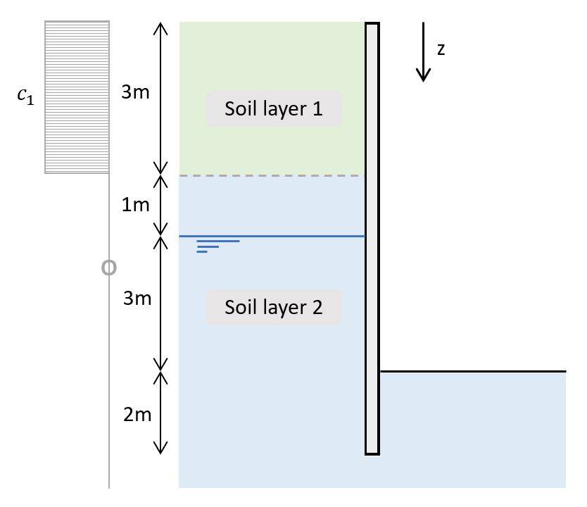
5. Cohesion
Cohesion describes how well the soil particles stick together. The cohesion of a soil layer is actually beneficial, meaning that it reduces the lateral load on the retaining wall.
The cohesion is calculated as:
Cohesion of active earth pressure
$$- 2 \cdot c_{ef} \cdot \sqrt{K_a}$$
Cohesion of passive earth pressure
$$+ 2 \cdot c_{ef} \cdot \sqrt{K_p}$$
| c [kN/m2] | ||
|---|---|---|
| c1 | $2 \cdot 2.5 kN/m^2 \cdot \sqrt{0.4}$ | 3.1 |
| c2 | $2 \cdot 0 kN/m^2 \cdot \sqrt{0.29}$ | 0 |
| cp | $2 \cdot 0 kN/m^2 \cdot \sqrt{3.1}$ | 0 |
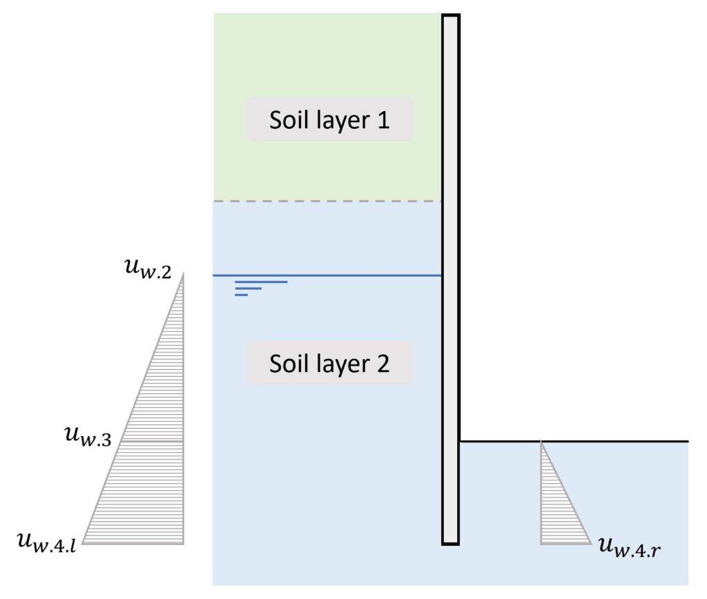
6. Hydrostatic water pressure
The groundwater below the groundwater table also exerts load on the retaining wall. The pressure increases with increasing depth, which is calculated as hydrostatic water pressure.
The load distribution is triangular and the value of the hydrostatic pressure at depth z is calculated as:
Hydrostatic water pressure
$$u_w = \gamma_w \cdot (z – 4m)$$
Note that we subtract 4m from z because the groundwater table is 4m below the terrain.
In the next table, we’ll calculate the hydrostatic water pressure for different depths z.
| Depth [m] | uw [kN/m2] | |
|---|---|---|
| uw.1 | 0 | 0 |
| uw.2 | 4 | 0 |
| uw.3 | 7 | $\gamma_w \cdot (7m – 4m) = 30 kN/m^2$ |
| uw.3.l | 9 | $\gamma_w \cdot (9m – 4m) = 50 kN/m^2$ |
| uw.3.r | 2 | $\gamma_w \cdot (2m) = 20 kN/m^2$ |
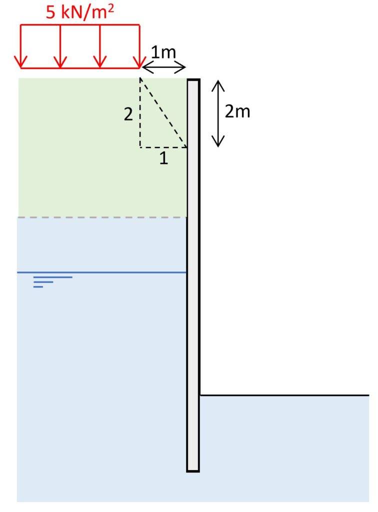
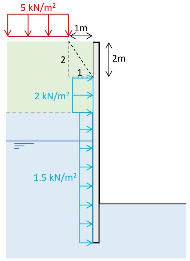
7. Load on terrain close to the structure
Another action on a retaining wall or sheet pile is a vertical load on the terrain close to the retaining wall.
This could be a live load from construction vehicles or even an existing building, a street or another permanent structure.
Let’s have a look at how we consider this situation.
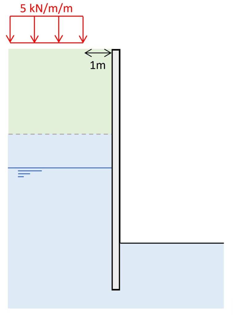
The vertical loading is located 1m away from the retaining wall. We can calculate the spread of the vertical stresses from this load with a 2V:1H slope.
Vertical stresses from vertical loading
$$\sigma_v = q = 5 kN/m^2$$
From the vertical stresses we can calculate the horizontal pressure on the underground structure which is uniformly distributed.
Horizontal pressure on wall
$$e = \sigma_v \cdot K_a$$
| e [kN/m2] | |
|---|---|
| Layer 1 | 2.0 |
| Layer 2 | 1.5 |
Conclusion
These are all the horizontal actions you need to consider when you design a retaining wall, basement wall or sheet pile. The next step is to combine these characteristic loads in load combinations and calculate the total design pressure on the structure.
Once that is done, the internal forces and stresses in the structure and soil can be calculated and verified.

![Types of Loads on Beams [Full Guide]](https://www.structuralbasics.com/wp-content/uploads/2022/11/Types-of-loads-on-beams-768x439.jpg)
![Vertical Load Transfer In Structural Engineering [2025]](https://www.structuralbasics.com/wp-content/uploads/2024/09/Vertical-load-transfer-1-768x439.jpg)