Compression Verification Of Reinforced Concrete [Eurocode]
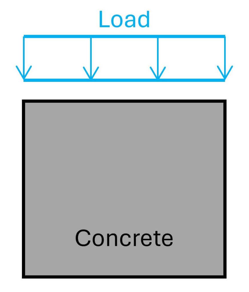
Concrete has a great compression capacity. Its tensile capacity, however, is very low. That’s the reason why reinforcement is added to most concrete elements.
In most cases, it’s not the concrete compression strength that’s critical, but the tensile strength of the reinforcement.
There are, however, a few design situations where the compression stress can be become greater than the compression capacity.
In this article, I’ll show you examples of critical situations for concrete compression, and the step-by-step process of verifying compression of concrete.
Let’s get into it.
Step-By-Step Process To Verify Compression Of Reinforced Concrete
Here’s the step-by-step process I always follow when verifying compression for reinforced concrete elements like walls, beams, columns, etc.:
Step #1: Defining the characteristic concrete strength fck
Step #2: Finding the partial safety factor γc
Step #3: Calculation of the design compression strength fcd
Step #4: Reduction factor ν (only for the compression strength of struts with ties)
Step #5: Verification of compression
Scroll down for an example where we run through all #5 steps in detail.
3 Examples Where Compression Needs To Be Checked
Throughout the years, I have developed an eye for situations where the compression strength might be critical.
When you start out as a graduate structural engineer, compressive concrete failure is usually not something you think of because concrete is great in compression, right?
There isn’t even a section for compression verification in Eurocode. Just about struts.
Here are 3 examples where concrete compression was critical in the projects I worked on.
Example #1: Column supporting a continuous wall
Reinforced concrete columns have a relatively big capacity for vertical loads compared to their cross-section. What often happens is that columns are verified with an Excel sheet or a software tool for its vertical and horizontal loads with M-N diagrams. Then, if the column doesn’t verify for these loads, “we just add reinforcement”.
I have experienced that the compression verification is often forgotten. The problem here is that we can’t “just add reinforcement”. Either the compressive strength of the concrete or the cross-sectional area needs to be increased.
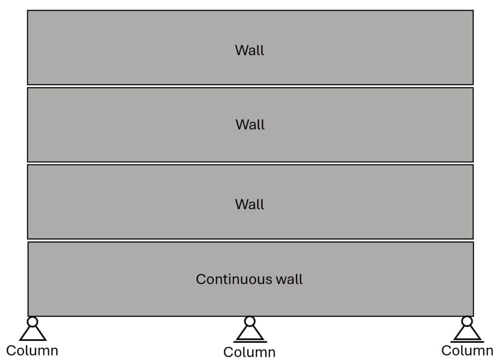
From my experience, the concrete compression strength becomes critical for center columns of relatively small cross-sectional area that support (continuous) walls from multiple floors.
In this scenario, the load on the continuous wall is quite big as it supports the walls and slabs of multiple stories.
And as we know, the center support (=column) takes up much more load than the other 2 supports.
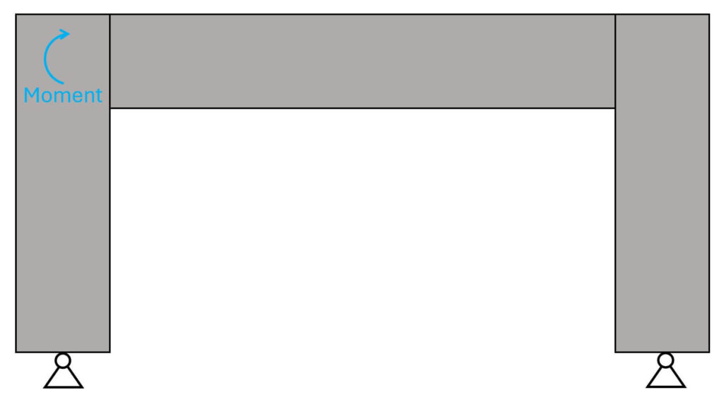
Example #2: Struts of moment stiff corners of frames
Frames can be used to stabilize a building and resist the horizontal loads. But also vertical loads.
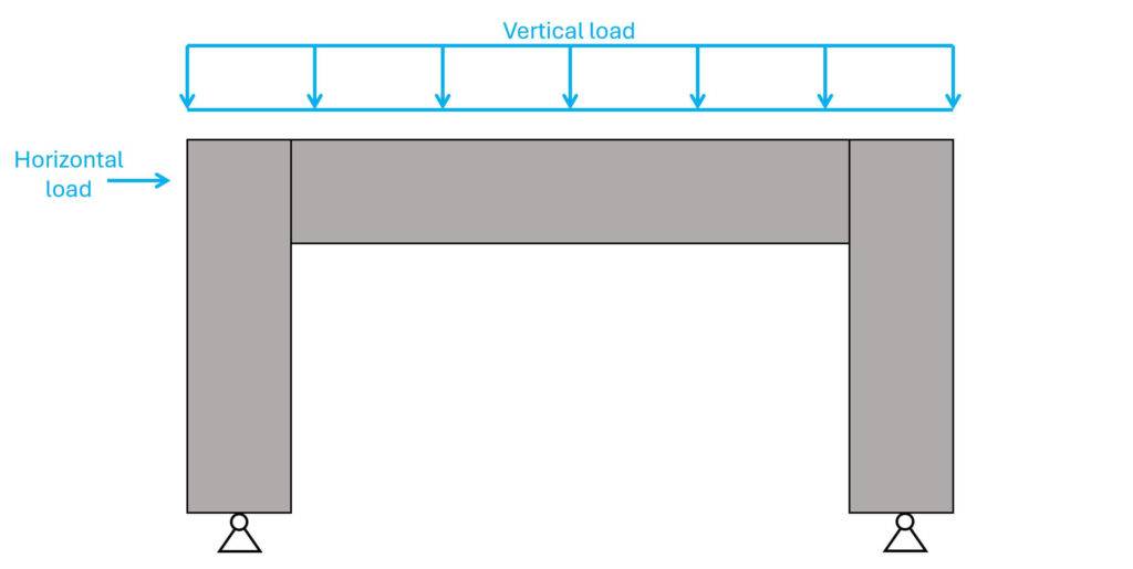
These horizontal and vertical loads lead to a bending moment in the corners.
One method to design and verify the corners for this bending moment is the strut & tie method. This method splits the structure into struts (compression members) and ties (tension members).
The axial forces of the struts are taken up by the compressive strength of concrete and the axial forces of the ties by reinforcement.
The bending moment from the picture above can now be split up into compression and tension forces (C = T = M/a).
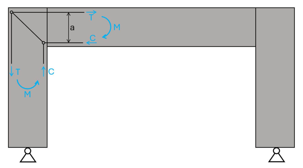
The reinforcement will then be verified for the tensile force T and the concrete for C.
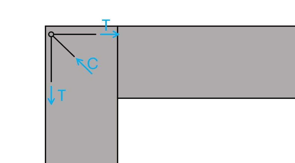
But what’s even more critical is actually transferring the tensile force T to the diagonal strut.
Whenever I designed a rc frame like this, I had to increase the cross-section of the frame.
C is calculated by either horizontal or vertical equilibrium. The tricky part here is that the tensile force T somehow has to be transferred from the reinforcement to the concrete, and we don’t have any anchorage here.
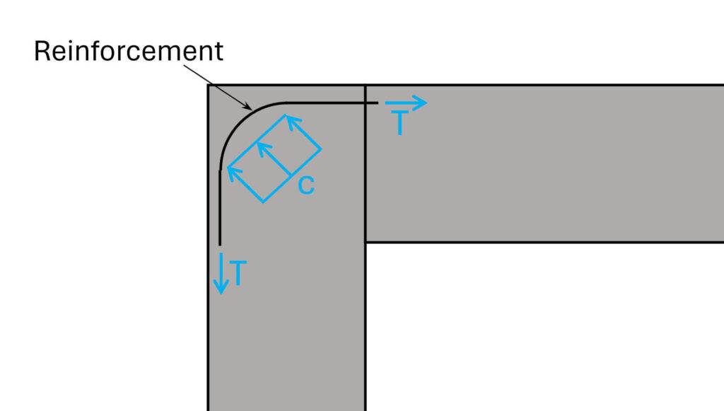
One way of doing it is to use the area of the bending radius of the reinforcement. But as you can imagine, the area isn’t that big to transfer the load C to the concrete and therefore the local compressive stress of the concrete can get quite big.
→ The smaller the area, the bigger the compressive stress. ←
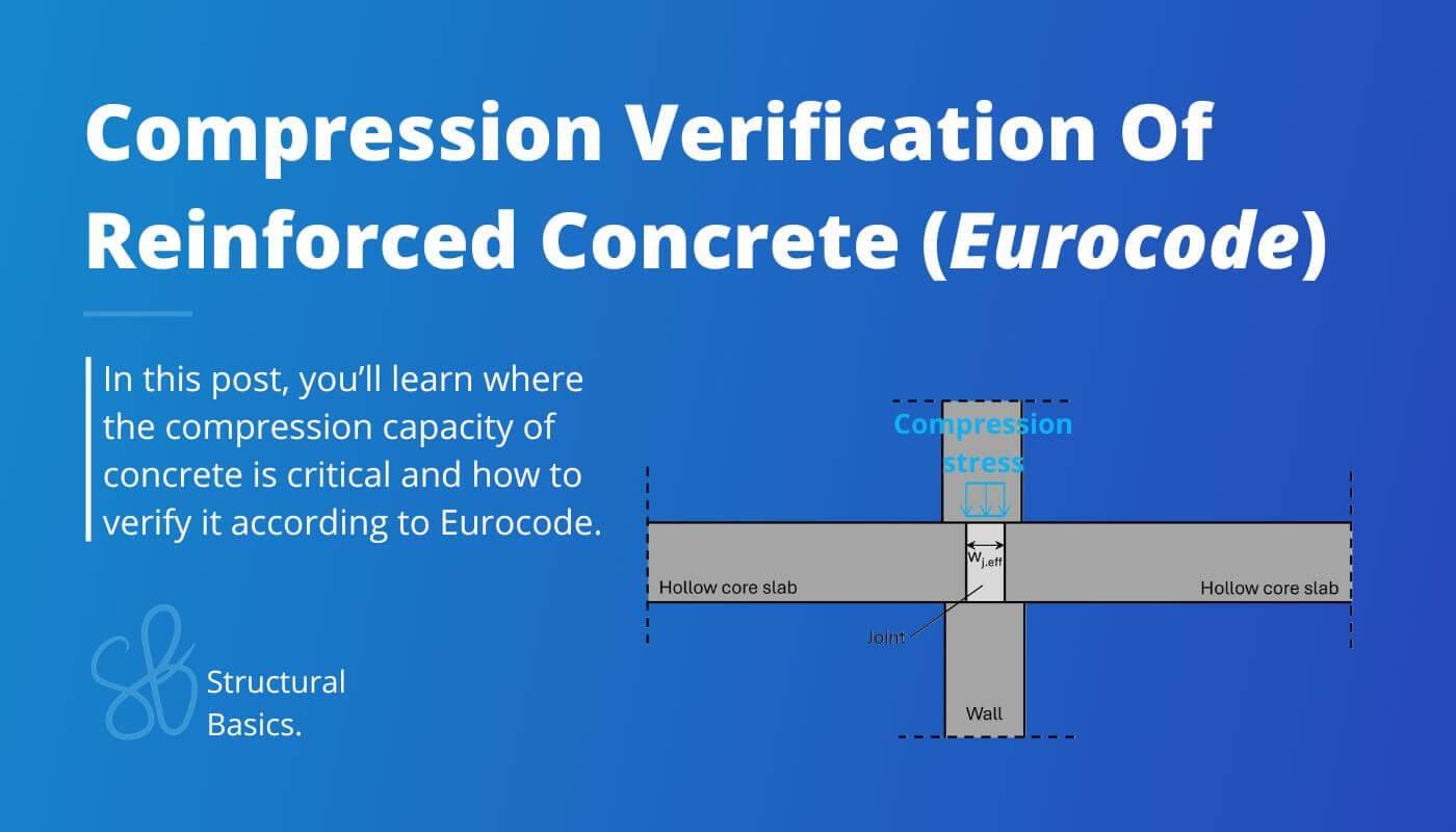
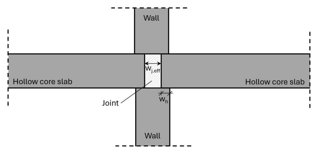
Example #3: Joints of precast concrete buildings resisting loads from shear walls
The vertical loads from precast concrete walls travel through the joint to the wall element below. This might be critical because wj.eff is in many cases much smaller than the width of the walls.
Hollow core slabs usually don’t take up the vertical load. With this smaller width, the compressive stress is much bigger in the joint than in the wall.
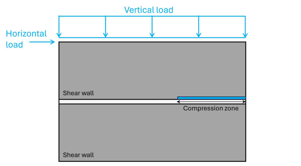
This becomes even more critical if the wall is a shear wall because in this case the vertical load is concentrated on an even smaller length (in the direction of the wall).
Because of the horizontal load, suddenly all the vertical load is transferred to the wall below in a much smaller length (compression zone).
Alright, now let’s look at how we verify compression of reinforced concrete..
The 5 Steps To Verify Compression Of Reinforced Concrete
Step #1: Define the characteristic concrete strength fck
As a first step, we need to define the concrete strength. We find the concrete strength classes in EN 1992-1-1 Table 3.1. For this newsletter, we’ll use a concrete class of C30 which has a characteristic concrete strength of 30 MPa.
$$f_{ck} = 30 MPa$$
Step #2: Find the partial safety factor γc
From EN 1992-1-1 Table 2.1N and for ULS design situations we’ll find the partial safety factor for concrete as 1.5.
$$\gamma_c = 1.5$$
Note that these values are usually defined differently in the National Annex. Make sure to check it. In Denmark, for example, the National Annex defines different values for precast and in-situ concrete.
Step #3: Calculate the design compression strength fcd
The design concrete strength is calculated as:
$$f_{cd} = f_{ck} / \gamma_c = 30 MPa / 1.5 = 20 MPa$$
Now, for examples #1 and #3, this is the design compression strength that needs to greater than the design compression stress from the loading.
According to EN 1992-1-1 6.5.2 (1) fcd can be used as compressive strength if there is transverse compressive stress or no transverse tension stress.
But for example #2 (for struts with ties in the same node), we need to calculate a reduction factor which fcd is multiplied with.
Step #4: Reduction factor ν (only for the compression strength of struts with ties)
According to EN 1992-1-1 (6.57N) the reduction factor v is calculated as:
$$\nu = 1 – f_{ck}/250$$
In our example with concrete C30, this leads to:
$$\nu = 1 – \frac{\frac{f_{ck}}{MPa}}{250} = 0.88$$
With formula EN 1992-1-1 (6.56N), we can now calculate the design compression resistance of struts with ties:
$$\sigma_{Rd.max} = 0.6 \cdot \nu \cdot f_{cd} = 10.56 MPa$$
Suddenly the compression strength is much smaller.
Note, that values for v and σRd.max can be defined differently in the National Annex.
We’ll get more into detail with this in a future episode, when we cover strut & tie models.
Step #5: Verification of compression
In this last step, we’ll verify that the compression stresses from loads are smaller than the compression strength.
Let’s use example #3 with a line load of p = 400 kN/m and an effective width of the joint wj.eff of 50 mm.
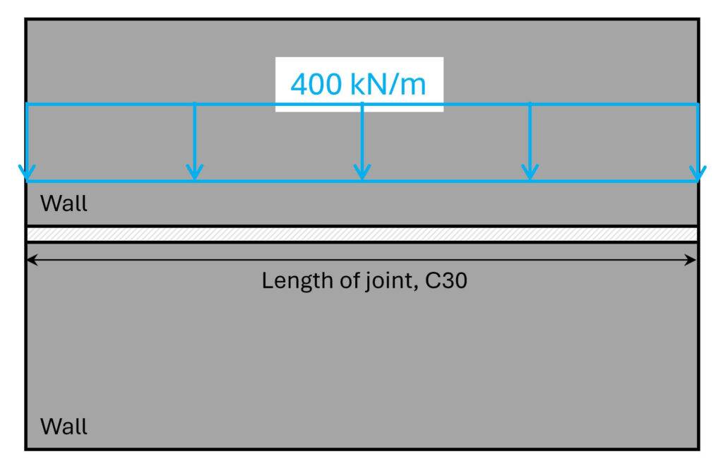
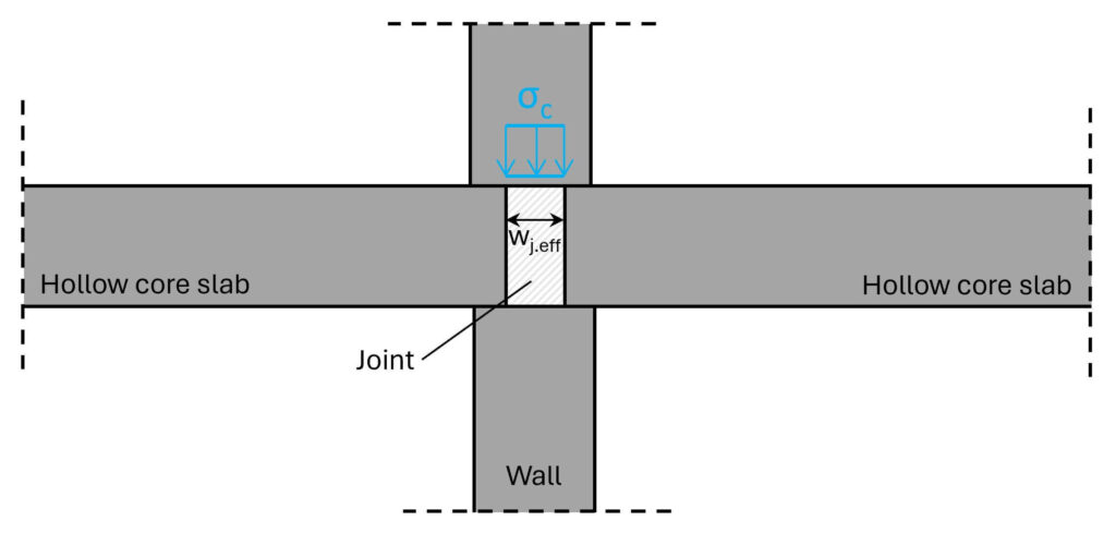
We then calculate the stress σc as:
$$\sigma_c = \frac{p}{w_{j.eff}} = \frac{400 kN/m}{50 mm} = 8 MPa$$
The utilization can now be calculated:
$$\eta = \frac{\sigma_c}{f_{cd}} = \frac{8 MPa}{20 MPa} = 40 \% < 100 \% \rightarrow OK!$$
The utilization is < 100% and the joint therefore verifies for the compression stress.
Final Words
As I said in the intro, I’ve seen a few projects where these compression verifications were forgotten.
I hope, after this article, you won’t forget the compression verification in your projects.
If you don’t want to miss any new structural design tutorials, then subscribe to our free weekly newsletter.

Laurin Ernst
![5 Timber Roof Structures Explained! [2025]](https://www.structuralbasics.com/wp-content/uploads/2022/01/Timber-roof-structures-768x439.jpg)
![Timber Truss Roof Design [A Structural Guide]](https://www.structuralbasics.com/wp-content/uploads/2022/04/Timber-Truss-Roof-Design-768x439.jpg)
![Timber Beam Design [Step-By-Step]](https://www.structuralbasics.com/wp-content/uploads/2022/01/Wood-timber-beam-design-Bending-moment-shear-and-deformation-verification-kmod-strength-768x439.png)