The Strut & Tie Method to Design Corbels, Pile Caps and Frame Corners
The strut & tie method is a design method used for reinforced concrete structures to design and verify elements like corbels, pile caps and frame corners.
In this article, you’ll learn how to draw up strut & tie models for pile caps, frame corners and corbels and how to design and verify corbels with the strut & tie method according to Eurocode.
Now, let’s get into it.
What is the Strut & Tie Method?
The strut & tie method is a lower-bound (=conservative) design method for reinforced concrete structures.
It’s often used for the design and verification of D-regions (“D”= discontinuity or disturbed) like for example frame corners, pile caps, corbels, capped ends and openings.
D-regions are regions in structural elements where the beam theory (Bernoulli’s beam theory) is no longer valid:
- The plane section does not remain plane because of nonlinear strain distribution
- The beam thickness does change
- The plane section does not remain normal to the neutral axis because the shear strains become large
D-regions appear in elements that have a large height-length ratio and are usually located where load are applied or close to supports.
The strut & tie method consists of only bar elements – struts and ties.
- Struts are compression members (=concrete) and
- Ties are tension members (=reinforcement)
A strut & tie model is basically a truss with bar elements and hinges at the nodes.
The method consists of 3 verifications:
1. Struts (=concrete) are verified for compression
2. Ties (=rebars) are verified for tension and
3. Nodes are verified for compression and correct anchorage of the reinforcement
The strut & tie method needs a lot of practice, and there are often multiple ways to draw the struts and ties.
In this article, you’ll learn how to draw strut & tie models for pile caps, frame corners and corbels and how to design and verify corbels with the strut & tie method according to Eurocode.
Here are 3 examples of reinforced concrete elements which can be designed with the strut & tie method
Pile caps
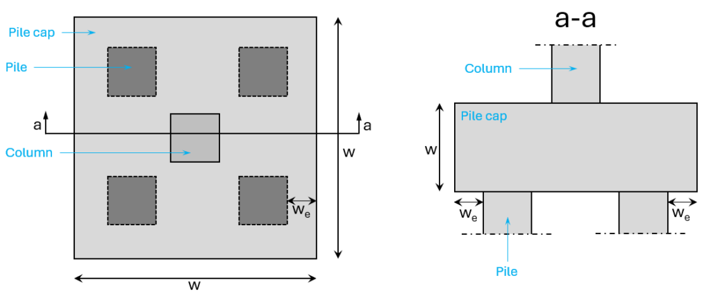
Pile caps are used to transfer point loads from columns to piles. The number of piles used and the geometry of the pile cap depends on the magnitude of the load from the column. In the image below, you see an example of a pile cap with 4 piles.
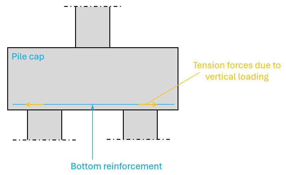
The strut & tie model of this pile cap with a vertical load from the column in a 2d section has 2 struts transferring the point load to the piles and a horizontal tie taking up the horizontal force which results from the inclination of the struts.
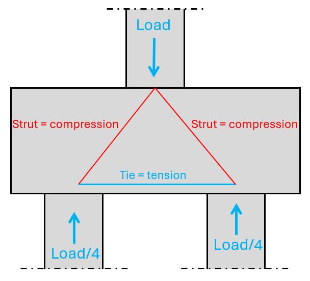
The compression in the struts is taken up by the compression strength of the concrete and the tension in the ties by reinforcement.
We’ll run through the whole calculation process of pile caps in a future episode. There are quite a few geometrical demands that need to be fulfilled.
Moment stiff frame corners
Reinforced concrete frames are used to resist vertical and horizontal loads. Walls with openings are another example for frames.
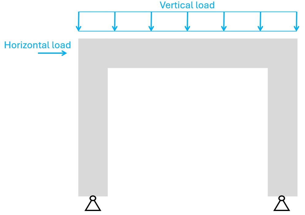
Due to the vertical and/or horizontal loads, a bending moment acts in the frame corners.
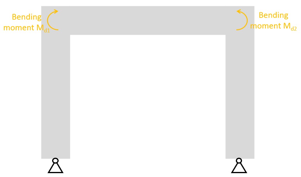
Now, the beam and columns have to resist these bending moments. This is a classic reinforced concrete bending verification of the cross-section, where the concrete takes up the compression and the reinforcement the tension.
But another thing we need to verify in the corners is that the bending moment can be transferred from the beam to the column or in reversed order. You guessed it, we do that with the strut & tie method.
First, the bending moment Md1 is split up into a compression (strut) C and a tension (tie) T member by calculating T=C=Md1/e. Second, we draw the strut & tie model. Remember, it’s up to the engineer how to draw the strut & tie model. There’s not just one solution.
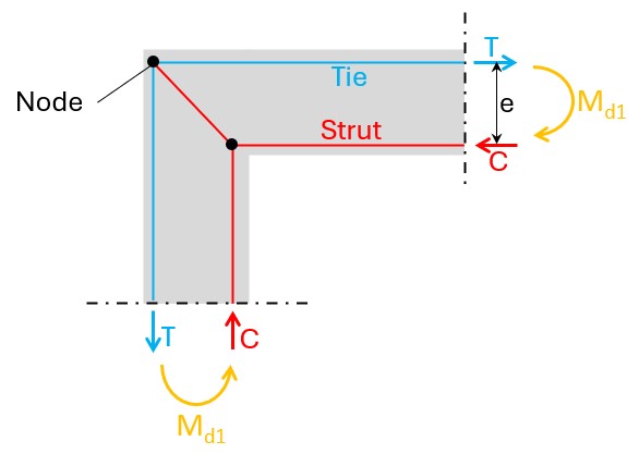
One thing is to verify the struts for compression and the ties (rebars) for tension, but another things is to verify the nodes. This is from my experience the most critical part. In our example, we need to transfer all the tension force T into the concrete. But we only have the bending radius of the rebars as an area.
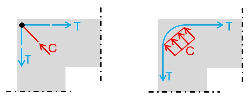
There is a section within Eurocode 2 that allows us to increase the concrete area that resists the compression stresses, but we basically have to verify that the compression stresses transferred in the bending radius of the rebars are smaller than the compression capacity of the concrete.
But we’ll dedicate a whole article about reinforced concrete frames, where we’ll dive deeper into this.
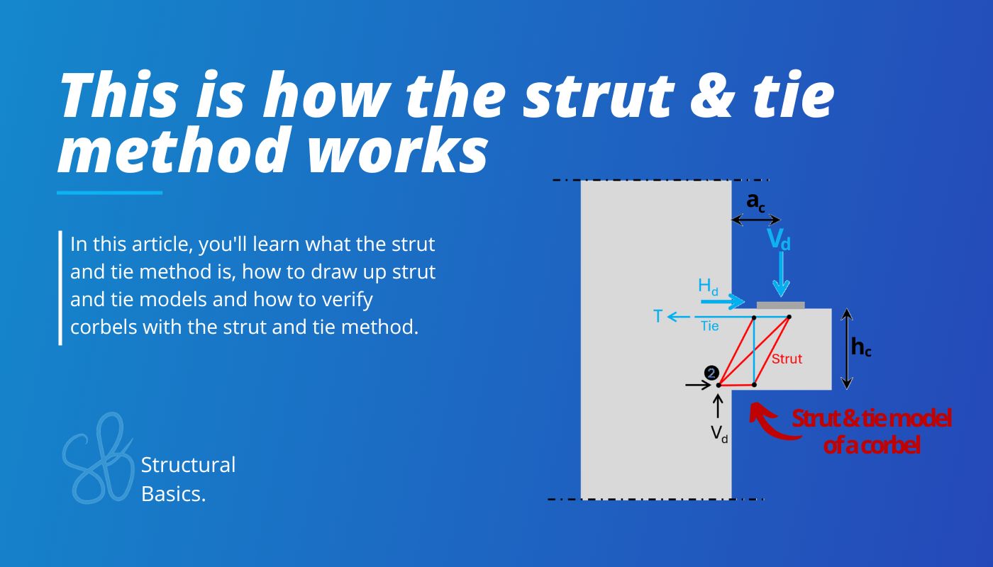
Corbels
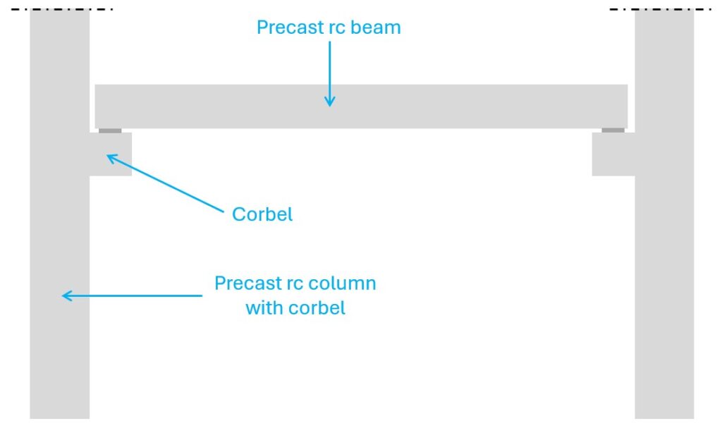
Corbels are often used in building and industrial structures to support beams, slabs and crane runway beams. They find use especially in precast elements like walls and columns. Here’s a very simplified example of a column with a corbel supporting a precast beam.
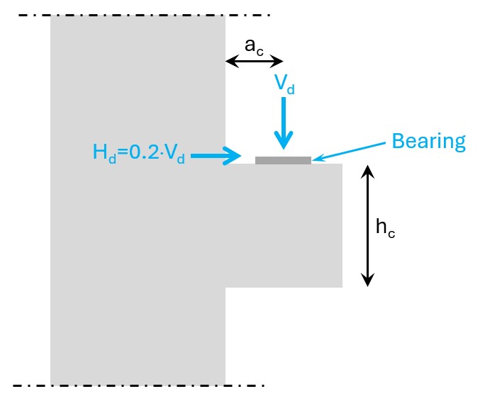
Now, let’s look a bit closer. According to Eurocode and other literature [1], there are 3 different types of corbels, which depend on the hc to ac ratio. These 3 types have different strut & tie models.
According to EN 1992-1-1 Figure J.5 and Mosley, B., Bungey, J., Hulse, R. (2012) [2] the corbel is also exposed to a horizontal force Hd. Hd should be taken as 0.2 of the vertical load Vd and it’s due to creeping, shrinking and temperature changes of the beam.
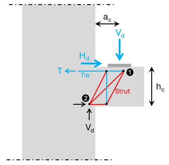
ac ≤ 0.5 hc
Unfortunately I couldn’t find names in English literature for the different types of corbels, because in German literature they have names which I find very helpful.
This type is called “gedrungene Konsole” in German which translates to “compact corbel” or “massive corbel”.
Here’s the strut & tie model of it.

The load in compact corbels travels directly from node 1 to node 2. Due to the compression stresses, the strut between node 1 and 2 expands which results in transverse tension. This transverse tension can be taken up by horizontal reinforcement, and therefore the horizontal tie is added.
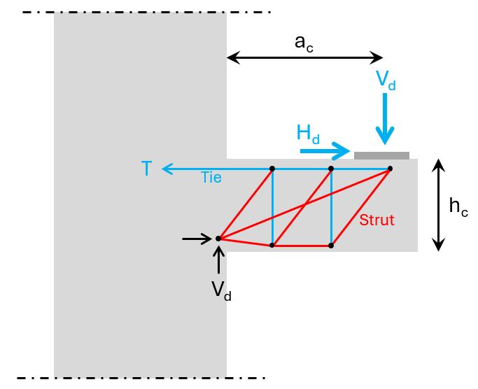
0.5 hc < ac ≤ 1.0 hc
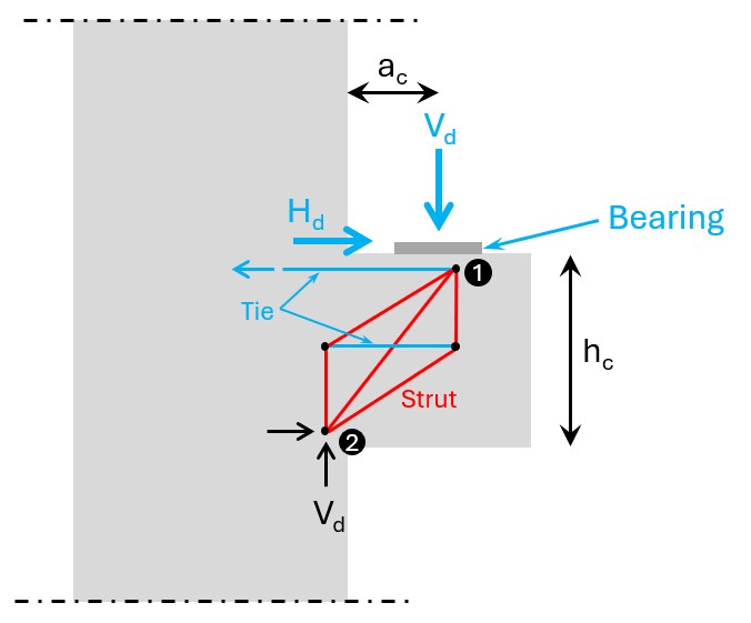
This type is called “schlanke Konsole” in German which translates to “slim corbel” and here’s the strut & tie model.
Slim corbels can transfer some of the vertical load directly to node 2 with the diagonal strut. However, because of its geometry (angle of the diagonal strut) some of the load needs to be “hung up” by a vertical tie from where it then travels to node 2.
ac > 1.0 hc
This type is called “sehr schlanke Konsole” in German, which translates to “very slim corbel” and it’s verified like a cantilever beam. Here’s the strut & tie model.
Alright, now let’s look at how we verify the ties (reinforcement), struts (concrete) and the nodes..
Design of Corbels with the Strut & Tie Method in 6 Steps
To run through the following verification steps, we’ll use the above example of a slim corbel. But let me know if I should do another article, about “compact corbels” and “very slim corbels”.
Let’s get into it..
Step #1: Define the geometry of the corbel
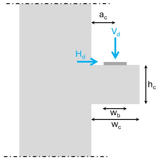
| Width of corbel | wc = 60 cm |
| Width of bearing | wb = 30 cm |
| Height of corbel | hc = 50 cm |
| Center of load to edge of column | ac = 30 cm |
| Vertical design load | Vd = 500 kN |
| Horizontal design load | Hd = 0.2 ⋅ 500 kN = 100 kN |
ac = 30 cm > 0.5 ⋅ hc = 25 cm → slim corbel
Next, we’ll draw up the strut and tie model of slim corbel.
Step #2: Draw up the strut & tie model based on the location of the load and the geometry of the corbel
We have already shown the strut & tie model of a slim corbel above, but here is it again.
Step #3: Calculation of T and its required reinforcement
We calculate the tension force T with moment equilibrium in node 2. But to calculate it, we need the distance between the top tie and the bottom strut. To do that, we subtract the concrete cover, the diameter of the vertical stirrups (assumption) and half of the diameter of the longitudinal rebars (assumption).
50 cm – 2 ⋅ 2.5 cm – 2 ⋅ 1.2 cm – 1.2 cm = 41.4 cm
Now, let’s set up the moment equilibrium:
$$\sum M = 0: T \cdot 41.4cm – V_d \cdot (a_c + 3cm) – H_d \cdot 41.4cm = 0$$
Solving this for T.
$$T = \frac{V_d \cdot (a_c +3cm) + H_d \cdot 41.4cm}{41.4cm} = 498.6 kN$$
From T we need to find a reinforcement diameter with the following parameters.
| Characteristic tensile capacity reinforcement | fy = 500 MPa |
| Partial safety factor reinforcement | γs = 1.15 |
(We use diameter 20mm, and we multiply by 4 because we use 4 rebars).
$$T_{Rd} = 4 \cdot \pi \cdot (20mm/2)^2 \cdot f_y/\gamma_s = 546.4 kN > T \rightarrow OK!$$
So, the top reinforcement is found! Check.
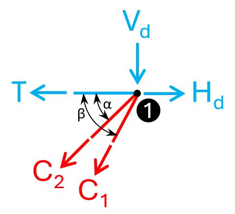
Step #4: Verification of node 1
In strut & tie models, there are different types of nodes that need to be verified. In our case, we have a compression – tension node.
Before we can verify anything, we need to find the normal forces of the 2 struts and the tie connected to node 1. Btw, a strut & tie model is basically a truss. You can read this detailed article on internal force calculation of statically determinate trusses.
This truss is unfortunately statically indeterminate, which means that we can’t solve the internal forces with the equilibrium equations. In node 1 we currently have 3 unknowns but only 2 equations (horizontal and vertical equilibrium).
Here’s the static system of the truss.
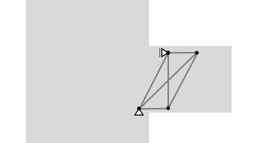
Checking the static determinacy:
- number of members m = 6
- number of support reactions r = 3
- number of joints j = 4
m + r = 9 > 2 ⋅ j = 8 → indeterminate
You see, these “boring” fundamentals we learned in the very first semester always come back.
Alright, as I said we can’t calculate statically indeterminate trusses with the equilibrium equations or other methods such as the method of joins or the method of sections.
There are luckily many truss calculators or FE programs out there. I used the SkyCiv truss calculator to calculate the normal forces. We can also check the reaction forces, which approves that we calculated T correctly.
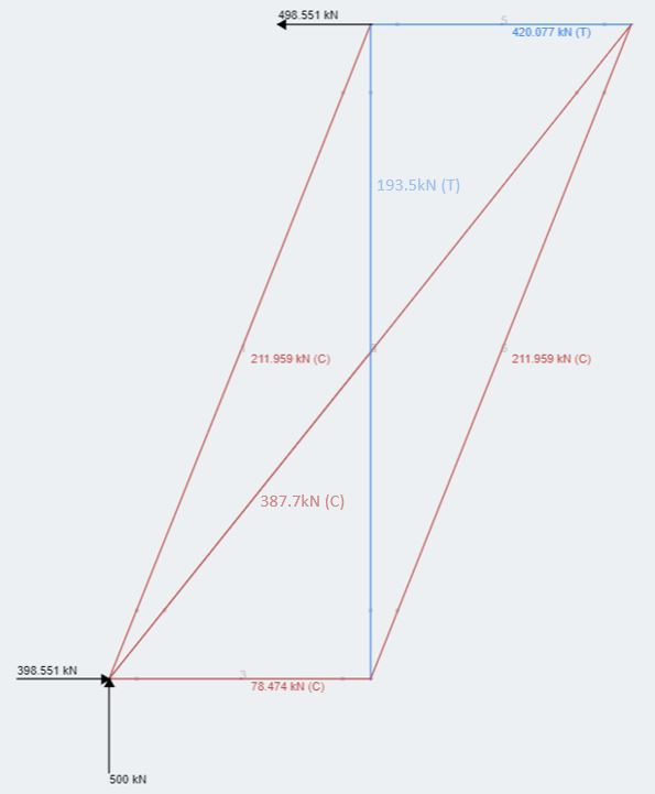
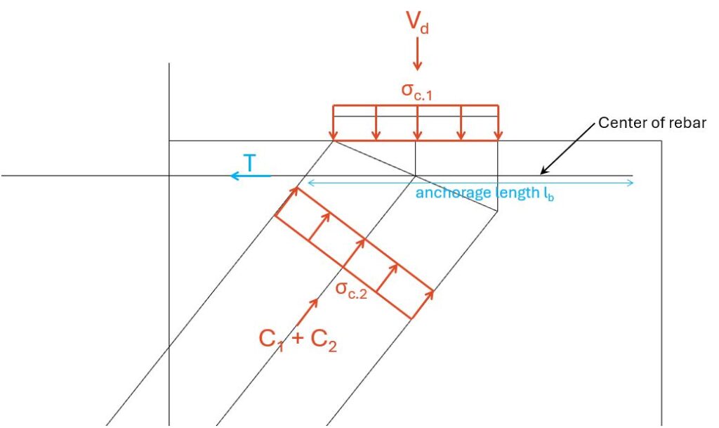
Back to node 1. We can now add the values for C1, C2 and T.
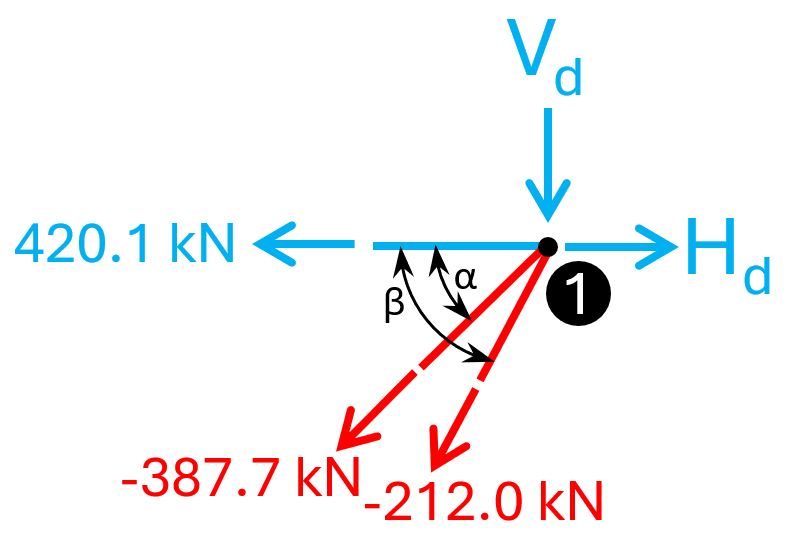
The dimensions of the struts C1 and C2 depend on whether the tie T can be fully anchored or not [1]. You can check out this article to learn how to anchor rebars correctly. For now, we’ll assume that the 4=20mm rebars are fully anchored.
We can then draw up the compression zone(s) in a CAD program. I use Rhino, because I got a licence a few years ago. In theory, the compression zone gets bigger the more downwards we go, because of C1. But we need to verify the compression stresses for the smallest area, which is the one I drew.
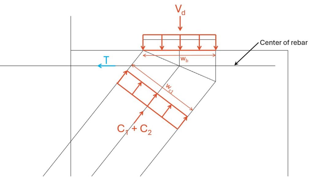
| Width of bearing | wb = 20 cm |
| Depth of bearing | db = 20 cm |
| Width of compression zone (measured in CAD program) | wc1 = 21.7 cm |
| Depth of compression zone | dc1 = 20 cm |
Here are the concrete properties:
| Characteristic compression capacity concrete C30 | fck = 30 MPa |
| Partial safety factor concrete (EN 1992-1-1 Table 2.1N) | γc = 1.5 |
| Reduction factor for struts with transverse tension (EN 1992-1-1 6.57N) | ν = 1-fck/250 = 0.88 |
| Design compression strength | fcd = fck/γc= 20 MPa |
Note that the parameter ν might be calculated differently in your National Annex.
According to EN 1992-1-1 (6.61), the compression strength of concrete in compression – tension nodes with anchored ties in one direction is calculated as:
$$\sigma_{Rd.max} = k_2 \cdot \upsilon \cdot f_{cd}$$
According to EN 1992-1-1 (6.61) Note, the recommended value of k2 is 0.85. A recommendation means that the value might be defined differently in your National Annex!
$$\sigma_{Rd.max} = k_2 \cdot \upsilon \cdot f_{cd} = 14.96 MPa$$
First, we’ll verify σc.1 and after σc.2.
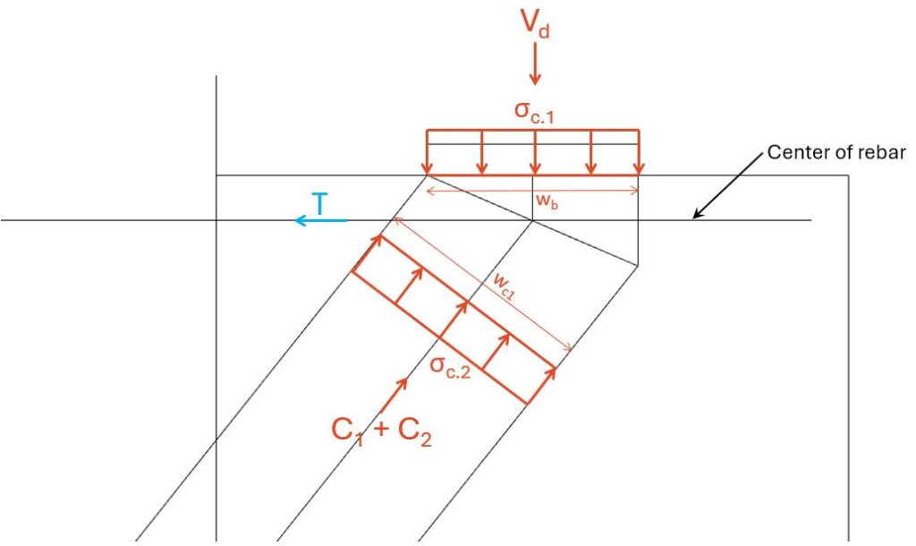
$$\sigma_{c.1} = \frac{V_d}{w_b \cdot d_d} = 12.5 MPa$$
Verification:
$$\eta = \frac{\sigma_{c.1}}{\sigma_{Rd.max}} = 0.84 < 1$$
$$\sigma_{c.2} = \frac{C_1 + C_2}{w_{c1} \cdot d_d} = 13.8 MPa$$
Verification:
$$\eta = \frac{\sigma_{c.2}}{\sigma_{Rd.max}} = 0.92 < 1$$
The only thing missing is the verification of the anchorage length.
We won’t do that now, as we have written a detailed guide on that a few weeks ago. But the anchorage length can be taken from the intersection of the rebars and the start of the compression zone to the end of the rebar.
Step #5: Design and verification of the vertical stirrups
Next, we’ll design the vertical stirrups which take up the tension force of 193.5 kN. We’ll use 3 stirrups of diameter 12mm.
$$T_{Rd} = 2 \cdot 3 \cdot \pi \cdot (12mm/2)^2 \cdot fy/\gamma_s = 295 kN > 193.5 kN$$
If you use more than 1 stirrup in your calculation, we need to make sure that the stirrups are placed within the compression area of the node. Otherwise the loads can’t be transfered.
Step #6: Reinforcement of the corbel
You should also design and verify the other nodes according to EN 1992-1-1 6.5.4. We don’t do it in this newsletter as it’s already a very long episode.
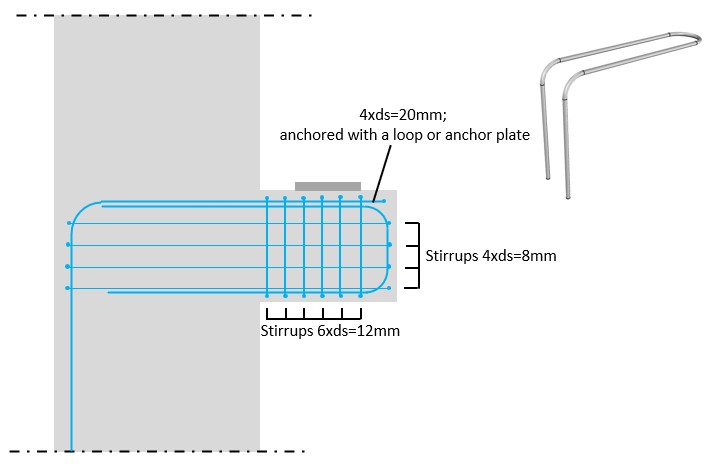
The last step is to do a reinforcement drawing or a sketch which you as an engineer send to your drafter.
Below you can see an example of a sketch. Note that we didn’t add any reinforcement of the column. This is because we only covered the corbels in this episode. The column need of course also reinforcement.
Final words
Alright, this was another super long and in-depth article. This was one of the top 5 articles that took me the longest to write. I wrote this article over a period of 2 weeks, and in total i spent probably arond 15-20 hours.
I hope this gave you a good introduction into the strut & tie method. It’s a complicated method which needs a lot of practice.
If you don’t want to miss any new structural design tutorials, then subscribe to our free weekly newsletter.
Or subscribe to my YouTube channel for regular updates.
Let’s design better structures together,
Laurin.

Laurin Ernst