Bending Verification Of Reinforced Concrete {Eurocode}
Bending is the verification I do the most when I design reinforced concrete elements as a structural engineer.
You need to verify bending when you design beams, slabs, frames, foundation beams, pad and strip footings and many more structural elements.
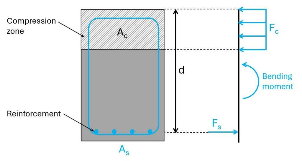
Concrete is great in compression but very weak in tension. The steel reinforcement is added to take up the tension forces. The bending moment of a rc cross-section is split up in a compression and a tension component, where the compression component is a compression zone taken up by the concrete and the tension force is taken up by the reinforcement as a tension force.
In this article, I’ll show how you design and verify reinforced concrete elements like beams and slabs for a bending moment in 6 steps.
Let’s get into it.
6 Steps To Verify Bending Of Reinforced Concrete
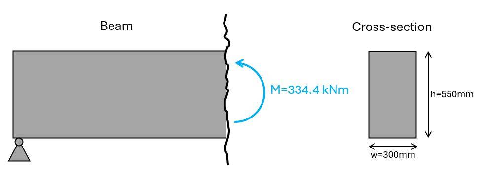
To run through the #6 steps to verify bending, we’ll use the following beam cross-section. You can apply this workflow also for slabs. Instead of the width of the beam in the formulas, use 1m.
In the literature, you can find many different formulas for the bending verification. The following formulas are the ones I use. Feel free to use different formulas if you want. Just know that there are options and the one I am presenting is not the one-and-only.
Also, every engineer has its own workflow. Some will first calculate the minimum reinforcement and other pick the reinforcement before they calculate the required reinforcement.
Therefore, feel free to swap around the following steps.
Step #1: Define the properties of concrete and reinforcement
In this tutorial, we’ll use the following concrete and reinforcement properties.
| Concrete compression strength | fc.k = 25 MPa |
| Concrete tensile strength | fctm = 2.6 MPa |
| Partial factor in-situ concrete (Denmark) | γc = 1.45 |
| Design compression strength | fc.d = fc.k/γc = 17.2 MPa |
| Design tensile strength | ft.d = fctm/γc = 1.8 MPa |
| Concrete cover | c = 30 mm |
| Reinforcement yield strength | fy.k = 550 MPa |
| Partial factor for reinforcement (Denmark) | γs = 1.2 |
| Design yield strength | fy.d = fy.k/γs = 458.3 MPa |
| For concrete C12-C50 | εcu3 = 0.35 |
| For concrete C12-C50 | εc3 = 0.175 |
| For concrete C12-C50 | λ = 0.8 |
| Reinforcement 550 MPa | εy.d = 0.208 |
| E-modulus concrete | Ecm = 31476 MPa |
| E-modulus reinforcement | Es = 200000 MPa |
Step #2: Calculate the lever arm of the longitudinal reinforcement
The lever arm is the distance from the most outer concrete fibre in compression to the longitudinal reinforcement taking up the tension forces.
In our example (for a positive bending moment), we’ll get compression in the top and tension in the bottom.
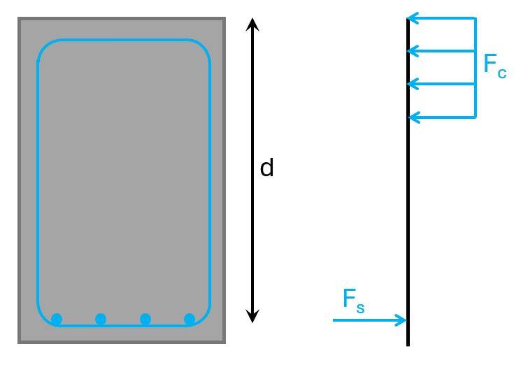
Let’s assume the diameter of the longitudinal reinforcement is ds = 25 mm and the stirrups dv = 10 mm, then the lever arm is calculated as:
$$d = h – c – d_v – d_s/2 = 498 mm$$
Step #3: Calculate the required longitudinal reinforcement to take up the tension force
The required reinforcement is calculated with the following formulas.
$$\mu = \frac{M}{w \cdot d^2 \cdot f_{cd}} = 0.261$$
$$\omega = 1- \sqrt{1-2 \cdot \mu} = 0.309$$
Required longitudinal reinforcement:
$$A_s = \omega \cdot \frac{w \cdot d \cdot f_{c.d}}{f_{y.d}} = 1735 mm^2$$
Step #4: Pick the diameter and amount of longitudinal reinforcement
We picked a rebar diameter of 25 mm, which has a cross-sectional area of:
$$A_{s.1} = \pi \cdot (\frac{d_s}{2})^2 = 490.9 mm^2$$
Next, we calculate the amount of rebars we need as a minimum to fulfill the required reinforcement demand:
$$\frac{A_s}{A_{s.1}} = 3.5 \rightarrow n = ceil(\frac{A_s}{A_{s.1}}) = 4$$
Now, we can calculate the total reinforcement area for 4 rebars of diameter 25 mm.
$$A_s = n \cdot A_{s.1} = 1963 mm^2$$
Step #5: Verify the degree of reinforcement
Now, we basically verify that the cross-section is not over and underreinforced.
$$\omega_{min} = max(0.26 \cdot \frac{f_{ctm}}{f_{y.k}} \cdot \frac{f_{y.d}}{f_{c.d}}, 0.0013 \cdot \frac{f_{y.d}}{f_{c.d}}) = 0.035$$
Verification:
$$\omega > \omega_{min} = 1 \rightarrow OK!$$
$$\omega_{bal} = \lambda \cdot \frac{\varepsilon_{cu3}}{\varepsilon_{cu3} + \varepsilon_{yd}} = 0.502$$
Verification:
$$\omega < \omega_{bal} = 1 \rightarrow OK!$$
$$\omega_{max} = 0.044 \cdot \frac{f_{y.d}}{f_{c.d}} = 1.17$$
Verification:
$$\omega < \omega_{max} = 1 \rightarrow OK!$$
Step #6: Verify the minimum reinforcement
The minimum reinforcement is calculated with EN 1992-1-1 9.2.1.1 (9.1N):
$$A_{s.min} = max(0.26 \cdot \frac{f_{ctm}}{f_{y.k}} \cdot w \cdot d, 0.0013 \cdot w \cdot d) = 194 mm^2$$
Now, comparing As with As.min shows that the minimum reinforcement is less than the reinforcement we get from 4 x d=25mm rebars.
$$A_{s.min} = 194 mm^2 < A_{s} = 1963 mm^2 \rightarrow OK!$$
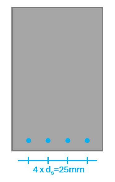
Now, this was only the verification for the bottom longitudinal reinforcement. Don’t forget to also verify the reinforcement in the top. If you don’t have negative moments, it should at least have the minimum reinforcement.
Final words
This is how you verify bending for reinforced concrete.
For many of you, this might have been repetition. But repetition is always good. It deepens your knowledge.
I also often gain new insights when I write and document these newsletters. Even though I have probably done this verification many times.
What happens in your day-to-day tasks as a structural engineer is that you use software for most verifications. So you actually don’t go through each step, we went through. But you definitely need to know what the software is doing.
Going through these hand calculations helps remember the formulas and fundamentals of reinforced concrete design. If we know the fundamentals by heart, we have a much better understanding of why a structure might not verify in a software program and how we can make it verify.
If you don’t want to miss any new structural design tutorials, then subscribe to our free weekly newsletter.

Laurin Ernst
![Timber Flat Roof Beam Design [Structural Calculation]](https://www.structuralbasics.com/wp-content/uploads/2022/04/Timber-flat-roof-design-768x439.jpg)
![Reinforced Concrete Column Design [2025]](https://www.structuralbasics.com/wp-content/uploads/2024/02/RC-column-design-768x439.jpg)
