Horizontal Load Transfer In Structural Engineering [2025]
When designing a building, my job as a structural engineer is to transfer vertical and horizontal loads through the building and down to the foundation, while verifying that all structural elements can resist these loads.
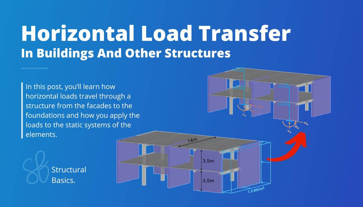
In this article, you’ll learn how the horizontal area load applied on a facade becomes a line load which acts on the floors and how this line load then turns into a point load on top of a shear wall.
We’ll run through 3 different examples because of the complexity of the topic.
Let’s get started. 🚀🚀
Step-By-Step Process To Transfer Horizontal Loads From Facades To Foundations
Here’s the step-by-step process I always follow when transferring horizontal loads through a building:
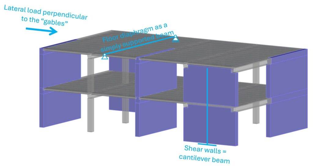
Step #1: Defining the static systems of the stabilizing elements (support conditions, hinge or moment stiff connections, etc.)
Step #2: Applying the horizontal loads like wind load, seismic load, earth pressure and/or imperfection load to the structural elements they act on
Step #3: Horizontal load transfer using the static systems
What Is Horizontal Load Transfer?
A building needs to transfer the horizontal and vertical loads that act on it down to the foundation. The loads travel from one structural element to another until they reach the foundation/soil. And of course all structural elements need to resist these loads.
We don’t use the same structural elements to resist horizontal loads as we do for vertical loads. Here are examples of structural elements that stabilize structures:
- Shear walls
- Floor diaphragms
- (Wind) braces
- Frames
Usually, a building/structure consists of at least 2 of these 4 stabilizing elements.
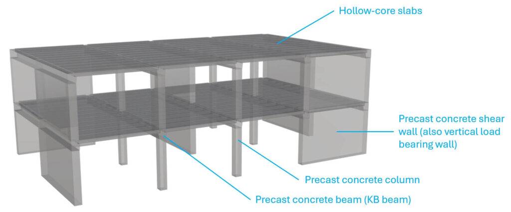
Example #1: Precast Concrete Building
The stabilizing elements of a typical precast concrete building are shear walls and floor diaphragms.
Now, I have also designed precast concrete buildings which included steel/concrete frames and braces. But typically, at least 90% of all stabilizing elements are shear walls and floor diaphragms.
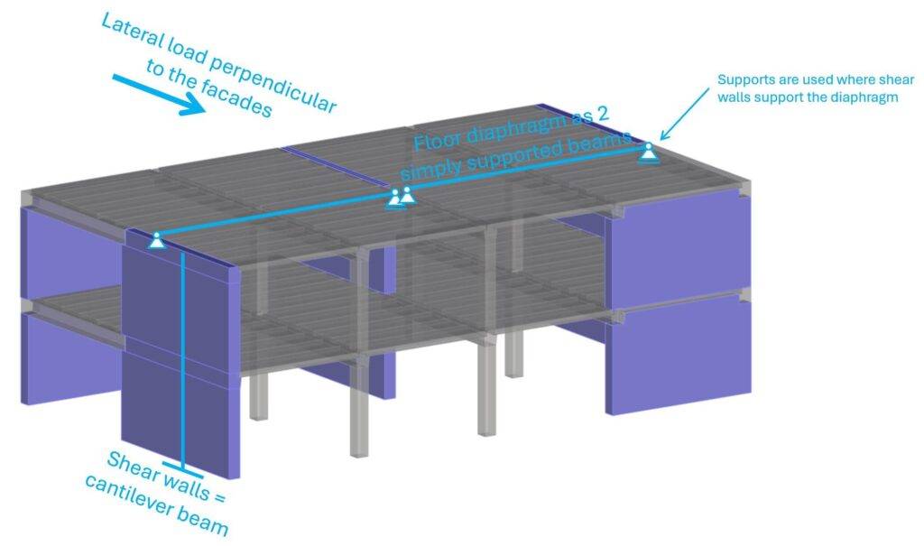
Step #1: Static systems of the stabilizing elements
Floor diaphragms are more tricky than other stabilizing elements and there are different methods to calculate these diaphragms but also to distribute the horizontal loads to the shear walls (elastic and plastic analysis).
As mentioned above, there are a few ways to distribute the horizontal loads to the shear walls. We can use an elastic or plastic distribution. More on these methods in another article.
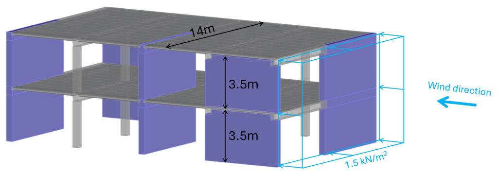
Step #2: Apply the horizontal loads
Let’s say the design horizontal wind load on the facade is 1.5 kN/m2 as the total of wind load area D and E. In the horizontal load transfer, we can simplify and apply the total load on one side of the building. But when you verify the diaphragms, you of course need to split them up and apply them separately.
Step #3: Load transfer using the static systems
We apply the load to the static system(s) and calculate the reaction forces. These reaction forces are then applied to the next structural element. We then again calculate the reaction forces of that element and apply it to the element that supports it.
The area load of 1.5 kN/m2 is applied to the facade. These facades distribute the area load to the floor diaphragms. Facade elements usually act as simply supported beams.
$$p_{d.f} = 1.5 kN/m^2 \cdot 3.5m/2 = 2.63 kN/m$$
This line load we can now apply to the floor diaphragms. We apply 2 ⋅ pd.f to the 1st floor.
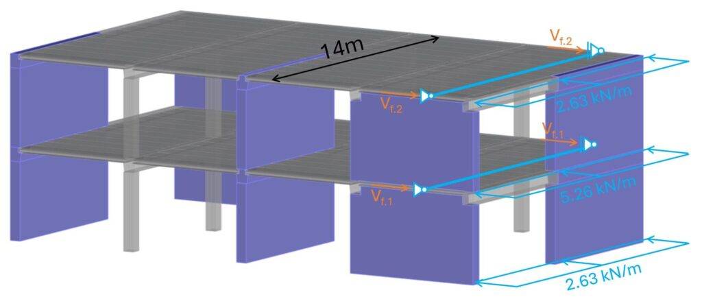
The reaction forces of the beams are calculated as:
$$V_f = p_{d.f} \cdot 14m/2$$
Which leads to the reaction forces of Vf.2 = 18.4 kN and Vf.1 = 36.8 kN.
Now, Vf.2 and Vf.1 are applied to the static system of the shear walls.
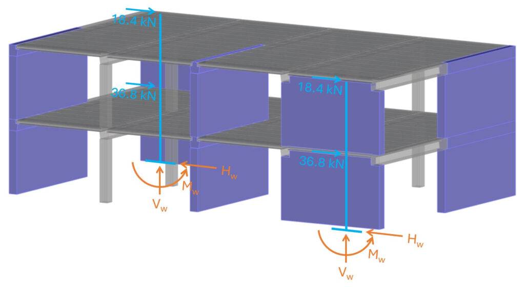
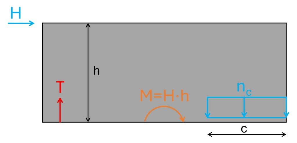
The horizontal loads on the shear walls lead to a bending moment at the bottom of the walls and a horizontal reaction force. This article isn’t about shear walls, but I also added a vertical reaction force because there are always vertical loads acting on shear walls.
And the bigger the vertical loads the better because it reduces the bending moment.
The bending moment is then transferred into a compression zone.
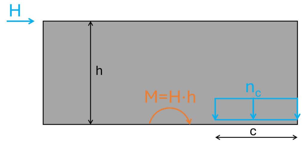
nc and c depend on the magnitude of M. The bigger M the smaller c which means that the bigger the eccentricity of the load. If c become too small, we add reinforcement at the other side of the wall to take up tension.
You can check out our article about precast shear wall design to learn how you do these verifications.
Example #2: Steel Warehouse
The next example is a steel warehouse that consists of frames and wind braces as the stabilizing elements.
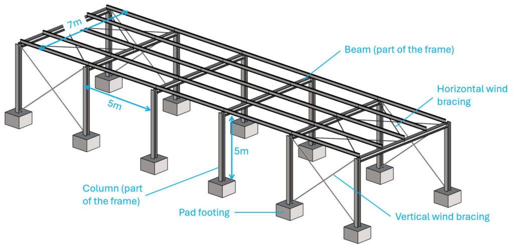
Step #1: Static systems of the stabilizing elements
In the scenario of lateral load acting perpendicular to the facades, the stabilizing elements are the frames.
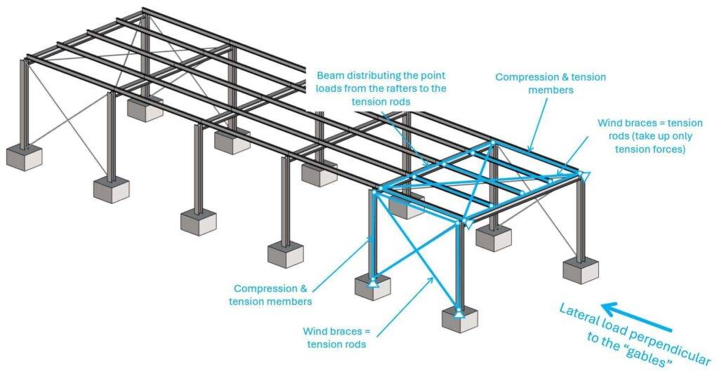
In the scenario of lateral load acting perpendicular to the gables, the stabilizing elements are wind braces, which act together with the rafters, beams and columns like a truss.
Step #2: Apply the horizontal loads
Let’s stick with the wind loading of 1.5 kN/m2.
Step #3: Horizontal load transfer using the static systems
Let’s split this up into lateral loading perpendicular to the facades and to the gables.
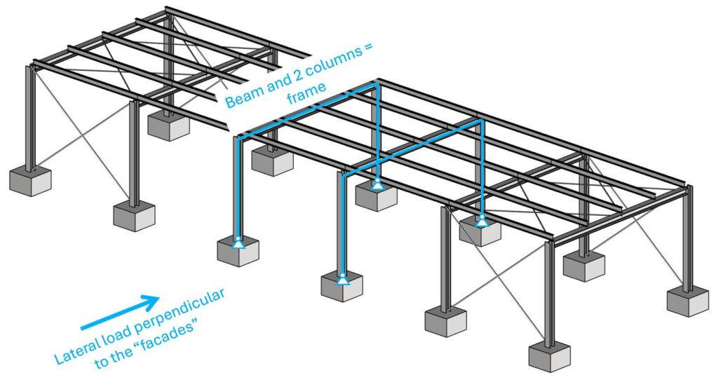
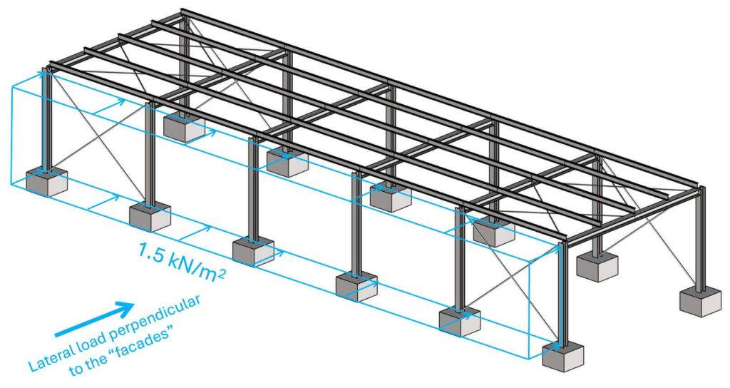
Lateral loading perpendicular to the facades
The area load of 1.5 kN/m2 is applied to the facade elements. These facades distribute the area load to the columns of the frame. You could also choose a design where the facade elements span vertically. Then the line loads would be applied to the roof and the foundation raft. In some warehouse designs you also see “horizontal purlins” which reduce the span of the vertical facade elements
The line load on the columns is calculated as:
$$p_{b} = 1.5 kN/m^2 \cdot 5m = 7.5 kN/m$$
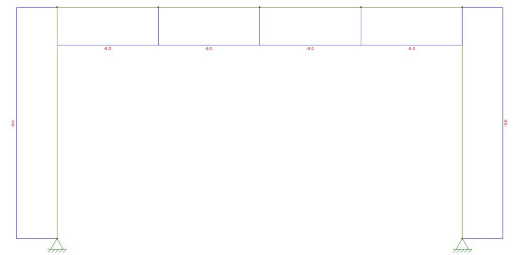
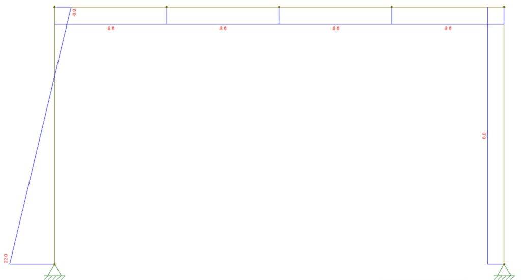
This line load we can now apply to the columns.
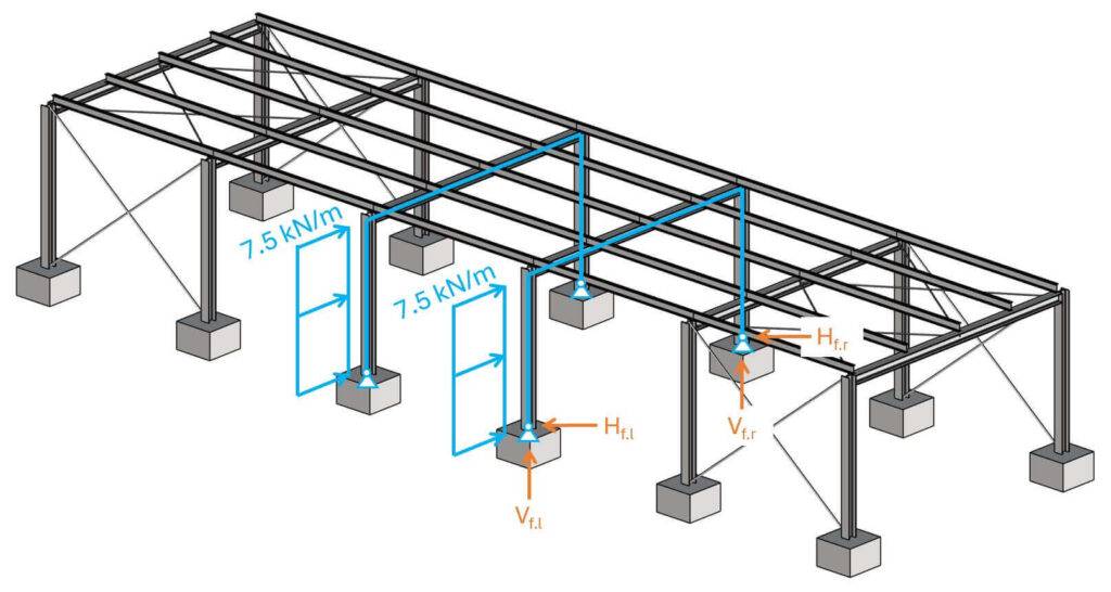
The frame is now transferring the horizontal loads down to the foundations with its moment stiff connections.
Modelling the frame in a frame analysis tool like Ftool or any FE program leads us to the reaction forces which the foundations have to be designed for.
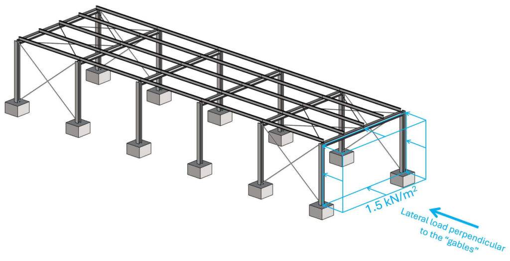
Lateral loading perpendicular to the gables
The area load of 1.5 kN/m2 is applied to the facade elements. These facades distribute the area load to the foundation raft and the beam of the frame.
The line load on the beam is calculated as:
$$p_b = 5 kN/m^2 \cdot 5m/2 = 3.75 kN/m$$
This line load we can now apply to the beam/truss. How the loads travel through the compression and tension members is a topic for another article.
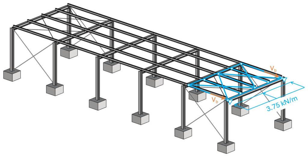
The reaction forces Vb are calculated like for a simply supported beam:
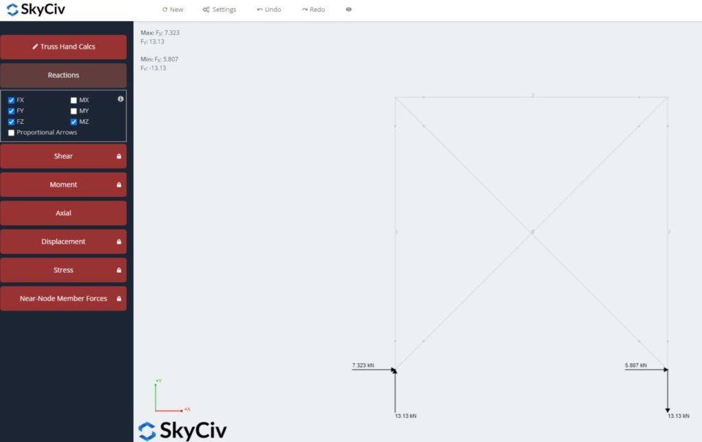
$$V_b = 3.75 kN/m \cdot 7m/2 = 13.13 kN$$
Vb can now be applied to the vertical wind bracing system.
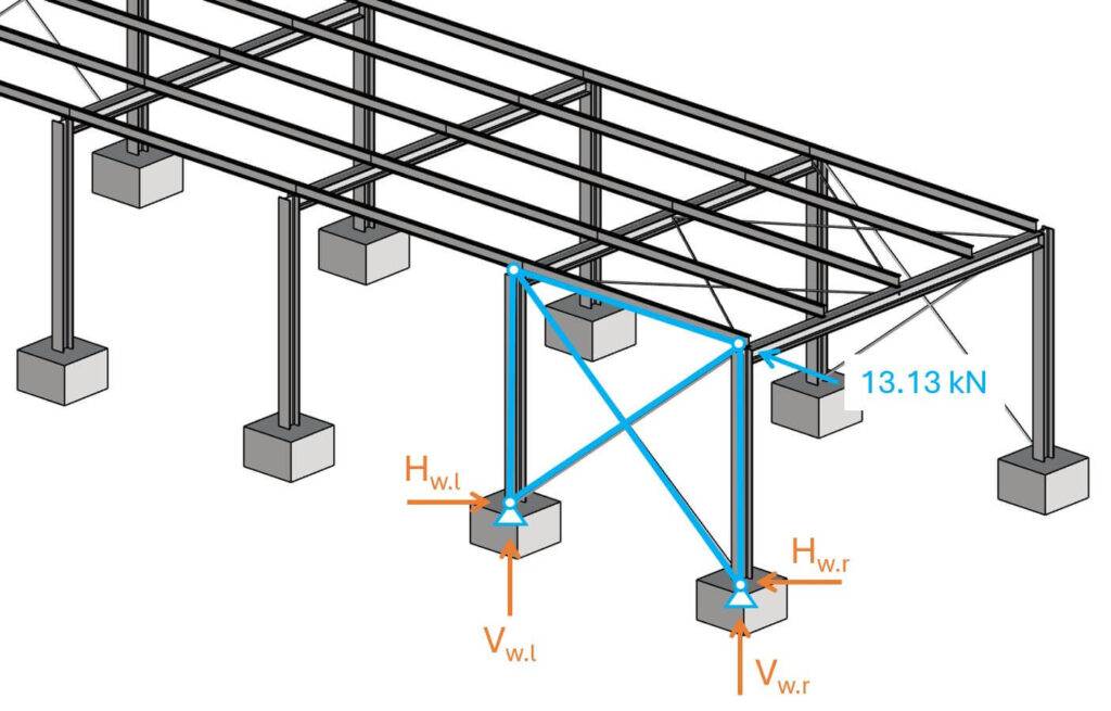
With the SkyCiv truss calculator, we calculate the reaction forces, because the static system is statically indeterminate.
Now, you can design the pad foundation with these reaction forces.
Final Words
3 examples of how to do horizontal load transfer. 💯💯
As already said, it’s a very complex topic, and it takes a lot of practice and experience to master.
I hope these examples with 3D visualizations helped you understand load transfer better. It took me hours to write this article and model the 3D structures in Rhino. I hope the hours I put into it were worth it.
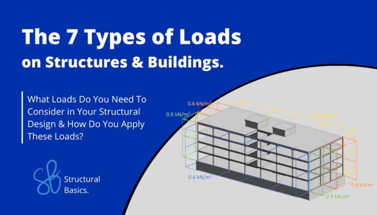
In this article, we assumed the loads. But if you are interested in learning how to calculate horizontal and vertical loads, then I recommend you check out our guide on the 7 different types of loads on buildings.

Laurin Ernst
![Vertical Load Transfer In Structural Engineering [2025]](https://www.structuralbasics.com/wp-content/uploads/2024/09/Vertical-load-transfer-1-768x439.jpg)